background image

Federal Communications Commission (FCC) Requirements, Part 15 

This equipment has been tested and found to comply with the limits for a class B digital device, 
pursuant to part 15 of the FCC Rules. These limits are designed to provide reasonable 
protection against harmful interference in a residential installation. 
This equipment generates, uses and can radiate radio frequency energy and, if not installed 
and used in accordance with the instructions, may cause harmful interference to radio 
communications. However, there is no guarantee that interference will not occur in a particular 
installation. If this equipment does cause harmful interference to radio or television reception, 
which can be determined by turning the equipment off and on, the user is encouraged to try to 
correct the interference by one or more of the following measures: 
---Reorient or relocate the receiving antenna. 
---Increase the separation between the equipment and receiver. 
---Connect the equipment into an outlet on a circuit different from that to which the receiver is 
connected. 
---Consult the dealer or an experienced radio/TV technician for help. 


Regulatory information / Disclaimers 

Changes or modifications not expressly approved by the party responsible for compliance 
could void the user's authority to operate the equipment. 


This device complies with Part 15 of the FCC Rules. Operation is 

subject to the following two conditions: 

(1) This device may not cause harmful interference. 
(2) This device must accept any interference received, including 

interference that may cause undesired operation. 


IMPORTANT NOTE (CO-LOCATION) 

FCC RF Radiation Exposure Statement: This equipment complies with FCC RF radiation 
exposure limits set forth for an uncontrolled environment. This device and its antenna must not 
be co-located or operating in conjunction with any other antenna or transmitter. The antenna(s) 


used for this transmitter must be installed to provide a separation distance of at least 20 cm 
from all persons.

Содержание 520G2006M1

Страница 1: ...Wireless Access Point User manual Page 1 of 1 Wireless Access Point User s Manual...

Страница 2: ...rease the separation between the equipment and receiver Connect the equipment into an outlet on a circuit different from that to which the receiver is connected Consult the dealer or an experienced ra...

Страница 3: ...the AP 134 Chapter 6 Web Configuration 171 6 1 Logging In 172 6 2 Status 194 6 3 LAN Setup 218 6 4 Wireless Settings 229 6 4 1 Basic Wireless Settings 231 6 4 2 Wireless Security 245 6 4 3 Wireless MA...

Страница 4: ...existing 802 11b infrastructure while migrating to the new screaming fast 802 11g The Wireless Access Point provides a total solution for the Small and Medium sized Business SMB and the Small Office H...

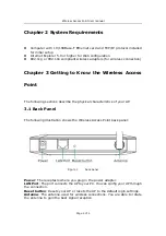
Страница 5: ...ccess Point The following sections describe the physical characteristics of your AP 3 1 Back Panel The following illustration shows the Wireless Access Point back panel Figure 1 back panel Power The r...

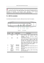
Страница 6: ...ght Status Description 1 PWR ON This indicator lights green when the Wireless AP is receiving power otherwise it is off 2 CPU ON The LED will be dark for a few seconds when the system is started After...

Страница 7: ...ng the hardware make sure to power off your Ethernet device and Wireless Access Point AP Then follow the steps below to connect the related devices Step 1 Connect your computer to the LAN port Attach...

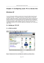
Страница 8: ...or wireless network The Wireless Access Point is configured with the default IP address of 192 168 1 1 and subnet mask of 255 255 255 0 and its DHCP server is enabled by default Before setting up the...

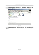
Страница 9: ...s Access Point User manual Page 8 of 8 Step 3 Highlight the icon Local Area Connection right click your mouse Click Properties Figure 4 Step 4 Highlight Internet Protocol TCP IP then press Properties...

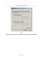
Страница 10: ...cess Point User manual Page 9 of 9 Figure 5 Step 5 Choose Obtain an IP address automatically and Obtain DNS Server Address automatically and then press OK to close the Internet Protocol TCP IP Propert...

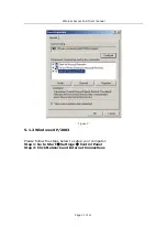
Страница 11: ...Wireless Access Point User manual Page 10 of 10 Figure 6 Step 6 Press OK to close the Local Area Connection Properties window...

Страница 12: ...ccess Point User manual Page 11 of 11 Figure 7 5 1 2 Windows XP 2003 Please follow the steps below to setup your computer Step 1 Go to Start Settings Control Panel Step 2 Click Network and Internet Co...

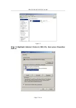
Страница 13: ...Wireless Access Point User manual Page 12 of 12 Figure 8 Step 3 Click Network Connections Figure 9 Step 4 Highlight the icon Local Area Connection right click your mouse Click Properties...

Страница 14: ...Wireless Access Point User manual Page 13 of 13 Figure 10 Step 5 Highlight Internet Protocol TCP IP then press Properties button...

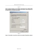
Страница 15: ...re 11 Step 6 Choose Obtain an IP address automatically and Obtain DNS Server Address automatically and then press OK to close the Internet Protocol TCP IP Properties window Figure 12 Step 7 Press OK t...

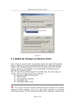
Страница 16: ...wireless adapter to use appropriate TCP IP settings as described in previous section Step 3 Launch the wireless adapter s provided utility and verify that your wireless client is configured with thes...

Страница 17: ...with the AP To execute the ping command open the DOS window and PING the IP address of the Wireless Access Point at the DOS prompt For Windows 98 Me Start Run Type command and click OK For Windows 200...

Страница 18: ...Wireless Access Point User manual Page 17 of 17 Figure 15 Verify your computer s network settings are correct and check the cable connection between the AP and the computer...

Страница 19: ...e the Wireless Access Point s web based configuration utility From now on the Wireless Access Point acts as a Web server sending HTML pages forms at your request You can click the menu options at the...

Страница 20: ...ions You can usually get context sensitive help by clicking on the Help link at the top right of the page Figure 17 To apply any settings you ve altered on any page click the Save button Otherwise you...

Страница 21: ...les or disables and display address pool Figure 19 Wireless Status This section shows the WLAN interface parameters of the wireless AP This includes information such as Wireless whether Wireless inter...

Страница 22: ...ess settings over the LAN interface Figure 22 IP Address Subnet Mask Gateway Enter the IP address Subnet mask and Gateway for the Wireless Access Point LAN port All local wired wireless devices commun...

Страница 23: ...d share the broadband Internet connection 6 4 1 Basic Wireless Settings The basic settings for wireless networking are set on this screen Figure 23 Radio Band The default setting is mixed mode 802 11B...

Страница 24: ...parameters 6 4 2 Wireless Security This wireless AP provides complete wireless LAN security functions include WEP WPA with pre shared key and WPA2 with pre shared key With these security functions you...

Страница 25: ...Selects 64 bit or 128 bit WEP encryption Be sure that the key length setting in the AP shall be the same as in wireless clients or the communication will not work WEP Mode You may select to select ASC...

Страница 26: ...lizes a stronger encryption algorithm and includes Message Integrity Code MIC to provide protection against hackers AES Advanced Encryption System AES utilizes a symmetric 128 Bit block data encryptio...

Страница 27: ...henticate and encrypt data transmitted in the wireless network The input format is in character style and key size should be in the range between 8 and 63 characters Clear If you want to retype again...

Страница 28: ...less MAC Filter This Wireless AP has the capability to control the wireless client access based on the MAC address of the wireless client The user has the flexibility to customize your own control pol...

Страница 29: ...tion Click Add Then this wireless station will be added into the Current Access Control List below If you want to remove some MAC address from the Current Access Control List select the MAC addresses...

Страница 30: ...Traffic Indication Message DTIM Lower settings result in more efficient networking while preventing your PC from dropping into power saving sleep mode Higher settings allow your PC to enter sleep mod...

Страница 31: ...r The DHCP server can be ON or OFF in this screen If you choose to set this device as a DHCP server then it will assign IP addresses to its clients The DHCP pool range is also changeable Figure 33 Set...

Страница 32: ...5 1 Login ID Password Setup In factory setting the default password is guest and that for user is also password You can change the default password to ensure that someone cannot adjust your settings...

Страница 33: ...y default settings Restore Factory Defaults To clear all of the AP s settings and reset them to its factory defaults Click the Restore Default button AP will restart automatically Restart System Click...

Страница 34: ...Reset the AP without Login Reboot the AP Press and hold the default button wait for a few seconds until the CPU LED indicator stays green After the above those steps the manufacture s parameters will...

Страница 35: ...11Mbps 9Mbps 6Mbps 5 5Mbps 2Mbps 1Mbps Security 64 128bit WEP WPA WPA2 Wireless MAC Filter Modulation Technology Orthogonal Frequency Division Multiplexing OFDM Receiver Sensitivity 54Mbps OFDM 10 PER...

Страница 36: ...Wireless Frequency Range 2 4GHz to 2 462GHz Wireless Operating Range Indoors up to 328ft 100M Outdoors up to 1312ft 400M Environmental factors may affect actual range Wireless Transmit Power 15dBm 2dB...

Страница 37: ...Wireless Access Point User manual Page 36 of 36...

Отзывы: