iBypass Switches with Heartbeat
18
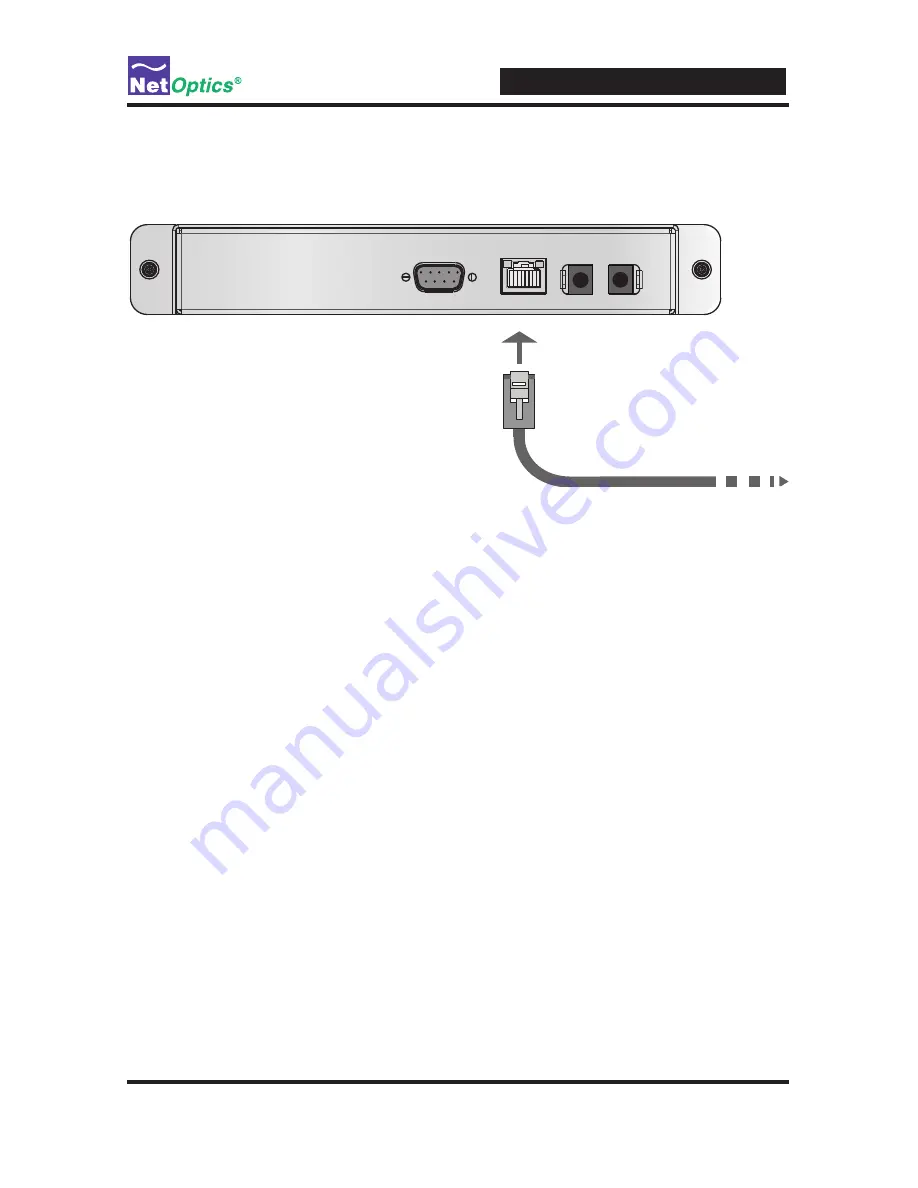
1. Connect a CAT5e cable to the Management Port as shown in the following figure.
2. Connect the other end to a network switch or hub.
To network switch or hub
Management
Port
RS232
Figure 9:
Connecting the Management Port
Disable, Enable and Check the Management Port
The CLI display command toggles the display on and off. From the terminal
emulation software, do the following:
1. Enter show display to view the current setting. The default value is ON.
2. Enter display. Now look at the front of the iBypass Switch. Access from the
Management Port is blocked and the iBypass Switch front panel does not display
utilization or peak information.
3. Enter display again to restore the display and remote interfaces.
Connect a Monitoring Device to the iBypass Switch
The iBypass Switch is delivered with two monitor cables for monitoring device
installation. Connect the cables to the monitoring device.
1. Connect Monitor Port 1 to the appropriate port on the monitoring device using
the LC type fiber cable or CAT5e copper cable.
2. Connect Monitor Port 2 to the appropriate port on the monitoring device using
the LC type fiber cable or CAT5e copper cable.


