22
© by NECTA VENDING SOLUTIONS SpA
0110 171-01
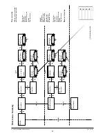
Fig. 13
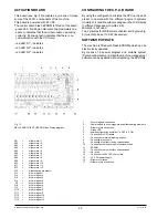
ACTUATION BOARD
This board (see Fig. 20) activates, by means of relays,
some of the 230V~ components of the machine.
This board is powered with 24 VDC.
The control board Flash EPROM is fitted on this board:
- green LED, blinking at intervals of approximately one
second, indicates that the microprocessor is working
correctly; if blinking fast it indicates that there is no
communication with the CPU card.
- red LED “H1”, indicates
- red LED “H2”, indicates
- red LED “H2”, indicates
CONFIGURING THE C.P.U. BOARD
By using the configuration minidips the CPU card can be
preset to operate with the different payment systems
(minidips 1-4) and show the messages on the LCD display
in different languages (minidips 6-8).
Minidip 5 is not used.
The 2 minidips for MDB coin mechanism setting (see Fig.
9) must both be set to OFF (Executive).
SOFTWARE UPDATE
The machine is fitted with Flash EPROMs which can be
electronically updated.
By means of a special program and suitable system
(Personal Computer or similar) the machine management
software can be updated without replacing the EPROMs.
RELAY AND TRIAC FUNCTION (see Wiring diagram)
K01
=
slider motor 1
K02
=
slider motor 2
K03
=
slider motor 3
K04
=
slider motor 4
K05
=
slider motor 5
K06
=
slider motor 6
K07
=
slider motor 7
K08
=
slider motor 8
K09
=
slider motor 9
K10
=
slider motor 10
K11
=
slider motor 11
K12
=
slider motor 12
K13
=
slider heating elements
Q3
=
drum magnet 1
Q4
=
drum magnet 2
Q5
=
drum magnet 3
Q6
=
drum magnet 4
Q7
=
drum magnet 5
Q8
=
drum magnet 6
Q9
=
drum magnet 7
Q10
=
drum magnet 8
Q11
=
drum magnet 9
Q12
=
drum magnet 10
Q13
=
drum magnet 11
Q14
=
drum magnet 12
1
- Drum magnets connection
2
- Power supply to drum magnets and slider heating elements
3
- Slider motors connection
4
- Green LED
5
- board configuration minidips 1-4: OFF 2-3: ON
6
- Connection to CPU board
7
- Connection to internal loading buttons
8
- Connection to sensors
9
- Connection to slider closing microswitches
10
- Connection to disk home point microswitches
11
- EPROM
12
- Connection to drum sectors microswitches
13
- Not used
14
- Connection to 230 VAC user relays
15
- 24 V DC power supply
16
- Slider motor fuses
17
- Slider motors connection
Содержание StarFood
Страница 1: ...INSTALLATION OPERATING AND MAINTENANCE MANUAL UK English StarFood DOC NO H 171U 01 EDITION 2 2001 10...
Страница 2: ......
Страница 4: ......
Страница 56: ...NECTA VENDING SOLUTIONS SpA...
Страница 57: ...Star ood...
Страница 58: ...NECTA VENDING SOLUTIONS SpA...
Страница 59: ...Star ood...
Страница 60: ...by NECTA VENDING SOLUTIONS SpA NOTE...
Страница 61: ...by NECTA VENDING SOLUTIONS SpA NOTE...
Страница 62: ...by NECTA VENDING SOLUTIONS SpA NOTE...
Страница 64: ......


