


12345
12345
12345
12345
12345
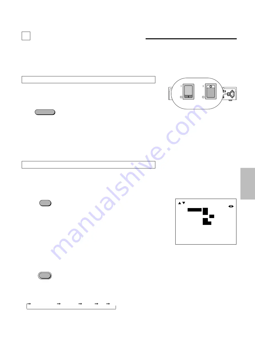
POWER
MAIN UNIT OPERATION
Connect input equipment as well as output equipment such as projectors prior to
operation. In this section, the following will be described: switching on and off the
power, on-screen displays used in adjustments and settings and their method of
use, selection of input equipment, selection of monitor output and scanning types,
and the muting of picture and sound.
Switching On and Off the Power
The POWER indicator will light green when the power is switched "ON".
The POWER indicator will light red when the power is switched "OFF" and the unit
will enter the standby mode.
To switch off the main power, set the POWER switch located on the rear panel
of the main unit to "OFF".
Notice
When the Auto Power function (described on Page 27) has been set, the unit can
be started up simply by switching on the main power.
Setting the POWER switch located on the rear panel of the main unit to "ON" puts
the unit into the standby mode. The power can then be switched on and off with
the front panel POWER button or the remote control POWER button.
Using the On-screen Display and the MENU Button
Switching the On-screen Display On and Off
This selection determines whether or not the displays for adjustment of the unit
and the settings are output from the OUTPUT connectors.
<Remote Control Only>
Each press of the DISPLAY button advances the setting of the on-screen output
between ON and OFF. The DISPLAY indicator of the main unit will be lit to indicate
that this function is ON.
When an operation is performed, notification is provided on the on-screen
display. Press the ENTER button to get rid of the display. (The displayed
information will automatically disappear when there has not been a button
operation for about 5 seconds.)
•
The on-screen display is not output from the MONITOR OUTPUT connector.
Note also that for signals input to INPUT 7 (RGB), the on-screen display will not
be output from the OUTPUT connector.
Using the MENU Button
Use the MENU button when making settings of V-APERTURE, MOTION, STILL,
NR, and SPLIT.
A press of the MENU button will bring up the on-screen display and each
subsequent press advances the selection one step in the sequence of
V-APERTURE
MOTION
STILL
NR
SPLIT.
See the various descriptions for information about the setting method.
A press of the MENU button while the CLT button is being held down will set the
SYSTEM setting mode and the on-screen display will be output.
See the method of making system settings of this setting method.
DISPLAY
MENU
The description will be explained when
the on-screen display is ON.
This may vary somewhat from the
display method of the main unit dis-
play window.
POWER
POWER
When ON
When OFF
ON
OFF
ON
OFF
ON
OFF
ON
OFF
H
-
V
-
H
-
V
+
H
+
V
-
H
+
V
+
DISPLAY
LCD LIGHT
AUTO POWER
IR RMT-CTL
SYNC
SYSTEM B
[
DBL
]
17


