background image

Monitoring the ft Server   4-13

Update

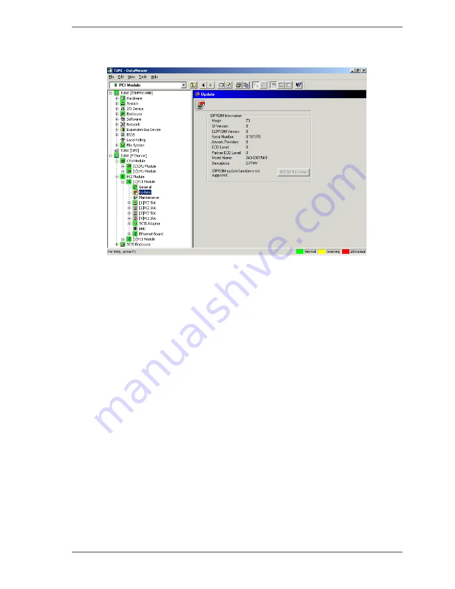
Select the 

Update 

folder. Data Viewer displays the PCI module 

Update

 screen.

The 

Update

 screen displays technical information about the selected Prom

located in the selected PCI Module.

Содержание Express5800 320La

Страница 1: ...L i n u x N e t w o r k O p e r a t i n g S y s t e m C o n f i g u r a t i o n G u i d e EXPRESS5800 320La 320La R...

Страница 2: ...factors such as system configuration customer data and operator control Since implementation by customers of each product may vary the suitability of specific product configurations and applications...

Страница 3: ...10 Confirming SCSI Disk Status 2 11 Setting SCSI Topology 2 13 Starting SCSI Disk s 2 15 Stopping SCSI Disk s 2 16 Adding Internal Disks 2 17 Replacing Internal Disk s 2 19 Replacing the Disk 2 20 Re...

Страница 4: ...3 24 BIOS and Agent Temperature Monitoring 3 25 Memory Error Alarm 3 25 Thresholds 3 25 Alerts 3 25 Warning Message about CPU Load 3 26 Stopping of the Primary PCI Module by the Server Utility 3 26 Co...

Страница 5: ...1 Introduction About this Guide Document Conventions How this Guide is Organized Related Documents Where to go from here...

Страница 6: ...m Document Conventions This guide uses the following text conventions Notes have the following meaning Note Notes give important information about the material being described The notational conventio...

Страница 7: ...iliar with your server documentation and to complete your installation successfully System User s Guide This guide provides a quick reference to information about your system Its goal is to familiariz...

Страница 8: ......

Страница 9: ...2 Configuring Linux Overview Powering up the Server Configuring the Network Interface Configuring Internal Disk Drives...

Страница 10: ...is information is intended to supplement the more detailed Linux procedural documents available from RED HAT Inc This information is not intended to be the central source of installation and configura...

Страница 11: ...rface controllers NICs and any installed network controller cards must be configured Onboard Integrated Network Interface Controllers Each PCI module in your server includes a 10BASE T 100BASE TX netw...

Страница 12: ...Metric 1 RX packets 4938 errors 0 dropped 0 overruns 0 frame 0 TX packets 0 errors 0 dropped 0 overruns 0 carrier 0 collisions 0 txqueuelen 100 Interrupt 15 Base address 0x8000 right epro09 06 DOWN Li...

Страница 13: ...P BROADCAST RUNNING MASTER MULTICAST MTU 1500 Metric 1 RX packets 0 errors 0 dropped 0 overruns 0 frame 0 TX packets 0 errors 0 dropped 0 overruns 0 carrier 0 collisions 0 txqueuelen 0 slot real statu...

Страница 14: ...ecognized the added NICs Note the slot number of the added NICs Type vndctl status Note An n in the commands in the next three steps indicates the slot number 1 6 of the slot containing the optional N...

Страница 15: ...verruns 0 frame 0 TX packets 0 errors 0 dropped 0 overruns 0 carrier 0 collisions 0 txqueuelen 0 slot real status link 7 left epro01 06 UP LINK Link encap Ethernet HWaddr 00 00 4C 0F F7 E0 UP BROADCAS...

Страница 16: ...The server also provides a single channel for general SCSI disks Channels for SCSI Disks PCI1 Channel1 SCSI Slot 1 2 3 PCI1 Channel2 SCSI Slot 4 5 6 PCI2 Channel1 SCSI Slot 4 5 6 PCI2 Channel2 SCSI S...

Страница 17: ...SLOT1 SLOT4 SLOT2 SLOT5 SLOT3 SLOT6 Note Paired hard disk drives in a RAID Level 1 configuration must have the same capacity and the same logical structure Using the ftdiskadm utility to manage your...

Страница 18: ...the status of all the internal SCSI disks Confirm RAID status of internal SCSI disks Recover RAID of internal SCSI disks Add internal SCSI disks Remove internal SCSI disks A ftdiskadm display sample i...

Страница 19: ...NSION name use serial tuple path sdg 0 0000924310220000 b3t0l0 d0h3c0t0l0 b2t0l0 d0h2c0t0l0 sdh 0 0000924310220001 b3t0l1 d0h3c0t0l1 b2t0l1 d0h2c0t0l1 sdk 0 0000924310220002 b3t0l2 d0h3c0t0l2 b2t0l2 d...

Страница 20: ...ware RAID device name partition Mount point or swap If neither mount point nor swap is displayed the RAID is configured but it is not mounted as a file system member Information of the members making...

Страница 21: ...L_NO Channel number The first channel number is 00 If multiple channels exist for a single SCSI bus a set of format and PCI_BUS_NO PCI_SLOT_NO CHANNEL_NO must be specified listed for each channel 3 If...

Страница 22: ...connects to Bus 1 Device b1t8l0 Host 09 05 Channel 1 connects to Bus 0 Device b0t8l0 Channel 0 connects to Bus 1 Device b1t8l0 Domain 2 Host 01 03 Channel 0 connects to Bus 2 Host 09 03 Channel 0 conn...

Страница 23: ...list enter An asterisk can be specified for TARGET and LUN A value 0 to maximum disk number of successfully started disks overrun count can be specified For TARGET the overrun count is the value speci...

Страница 24: ...p 5 Bring Down 9 RETURN Command 5 Bring Down Which disk s for help 10 1 t0l5 see Note 1 f Bring down 10 1 t0l5 d0h2c0t0l5 y n y Confirm the started SCSI disk s Notes 1 To obtain a disk specification m...

Страница 25: ...pecify a SCSI slot number with a disk inserted in the slot At this time another disk must also be inserted in the slot paired with the specified one 2 Enter the disk label if necessary If the disk is...

Страница 26: ...ber md0 boot boot DUPLEX 1 sda1 4 sdd1 md1 usr usr DUPLEX 1 sda5 4 sdd5 md2 home home DUPLEX 1 sda10 4 sdd10 md3 var var DUPLEX 1 sda6 4 sdd6 md4 DUPLEX 1 sda8 4 sdd8 md5 tmp tmp DUPLEX 1 sda9 4 sdd9...

Страница 27: ...ng from disk 3 removal to RAID restoration ftdiskadm Command action 1 SCSI 2 RAID 3 Environment 9 Quit Command 2 Command action 1 Status Raid 2 Status All Disks 3 Repair Disk 4 New Disks 5 Remove Half...

Страница 28: ...sdc6 6 sdf6 Command action 1 Status Raid 2 Status All Disks 3 Repair Disk 4 New Disks 5 Remove Half Disk 6 Remove Full Disks 9 RETURN The following is an example of restoring repairing RAID Step 3 of...

Страница 29: ...sdd10 md3 var var DUPLEX 1 sda6 4 sdd6 md4 DUPLEX 1 sda8 4 sdd8 md5 tmp tmp DUPLEX 1 sda9 4 sdd9 md6 swap DUPLEX 1 sda7 4 sdd7 md7 extra_s1 SIMPLEX 3 sdc1 6 sdf1 md8 extra_s5 SIMPLEX 3 sdc5 6 sdf5 md...

Страница 30: ...sult The Official Red Hat Linux Customization Guide Red Hat Linux 7 1 detailing all parameters of the files IMPORTANT Be sure to only append to the Post section of the kickstart file as all customizat...

Страница 31: ...e at purchase of the server For the factory set password see the attached paper Administrator root password provided with the server After logging in the system with root change to an arbitrary passwo...

Страница 32: ......

Страница 33: ...3 ESMPRO Agent for Linux NEC ESMPRO Agent Required Software Modules Installing the Agent Report Setting Agent Monitoring ESMPRO Agent Considerations Alert Report Device IDs...

Страница 34: ...ablish threshold limits for your server Required Software Modules Agent for Linux requires installation of the following software modules ucd snmp Linux module newt Linux module slang Linux module por...

Страница 35: ...t gives the public community READ WRITE access in the default etc snmp snmpd conf file Third create a view for us to let the group have rights to name incl excl subtree mask optional view all included...

Страница 36: ...functions of the installed NEC ESMPRO Agent are enabled when the system has restarted IMPORTANT To get NEC ESMPRO Agent to report data to NEC ESMPRO Manager set a reporting method by the report setti...

Страница 37: ...g all the current settings Selecting 3 terminates operation without installing NEC ESMPRO Agent 8 Restart the system The functions of the installed NEC ESMPRO Agent are enabled when the system has res...

Страница 38: ...elect the events you want the Agent to monitor Agents Events Setting and Syslog Events Setting Setting Manager Reporting SNMP 1 Log in the system as a root authorized user 2 Move to the directory cont...

Страница 39: ...access service over a dial up network WAN environment Shutdown Delay Enter a time period for the shutdown delay When the managed server receives a command to shut down it will first display a pop up m...

Страница 40: ...r s IP address in the Agent s list of SNMP trap destinations Trap Destination IP Specifies the manager console s IP address as a SNMP trap destination Select Add or Remove to change add or delete the...

Страница 41: ...ociate one or more destination IDs with the event number When the Agent detects that event assuming the Agent has been set to monitor that event number the Agent performs the action specified by the m...

Страница 42: ...ing menu above displays the Schedule menu A schedule can be set for each destination ID In the schedule set a report retry interval which is usually set in the range of 1 to 30 minutes Set the retry e...

Страница 43: ...the remote manager The default value is 31134 Manager TCP_IP Out of Band When you define a destination ID based on this method you provide RAS address information and can also specify a reporting sche...

Страница 44: ...menu Source The origin of a particular Agent event Event ID The destination ID of a particular Agent event Source The origin of a particular Agent event Event ID The destination ID of a particular Ag...

Страница 45: ...ets you configure internal events generated by the operating system Selecting Syslog Events Setting at the Report Setting menu displays the Syslog Events Setting menu Source The origin of a particular...

Страница 46: ...by the Agent Agent Properties are described in detail later in this chapter At the Agent you can establish threshold limits and reset values for a number of parameters These settings can also be made...

Страница 47: ...tdown or reboot A check gives the Manager permission No check denies the Manager permission Note Also enable Shutdown Delay in the Base Setting window of the Alert Manager Report Setting Utility ESMam...

Страница 48: ...this box to make these settings effective now Leave it unchecked to store settings for future use Thresholds can also be set in the Data Viewer at the ESMPRO Manager Fatal Report Limit When the CPU lo...

Страница 49: ...sk space used in units of percent Enable threshold the amount of free bytes KB When this bullet is indicated threshold settings for the drive are active The Report column shows the lower limit for the...

Страница 50: ...alert is cleared when the amount of used disk space falls below the value in the Warning Reset column When the bullet labeled Enable Threshold amount of free bytes KB is indicated this limit is the am...

Страница 51: ...y indicate that the network traffic is extremely heavy Try reducing the network traffic to this server Temperature Properties Temperature is measured by hardware thermal sensors On the Temperature tab...

Страница 52: ...High Reset Warning low report warning low limit When the temperature falls below this value a warning alert message is generated and the status of the Agent changes to warning The warning low limit mu...

Страница 53: ...on boards located within the PCI modules Voltage Sensor The name of the voltage sensor Upper Fatal The high voltage limit that triggers a fatal alert Upper Warning The high voltage limit that triggers...

Страница 54: ...server periodically and waits for a response The signal is sent at intervals defined by the Interval field If the server doesn t respond in the time period shown in the Timeout field the server is ass...

Страница 55: ...should take to complete a shutdown Action When Timeout When a the operating system takes longer to shutdown than the allotted time specified the Action When Timeout setting determines how the Agent re...

Страница 56: ...of Installation States of CPU and PCI Modules When you change the configuration of a CPU or PCI module using data viewer a message prompting you to reconstruct the tree of the data viewer displays If...

Страница 57: ...lues set in BIOS must also be set in the NEC ESMPRO Agent for the agent to correctly monitor temperature changes Memory Error Alarm If a memory error alarm is sent as a trap to the manager the bank ID...

Страница 58: ...events which do not permit NEC ESMPRO Agent to get information occur consecutively the displayed CPU load rate may be lower than the actual value Stopping of the Primary PCI Module by the Server Util...

Страница 59: ...SCSI adapter 1 on PCI module 1 Ethernet Board 1 on PCI module 1 Power supply unit on PCI module 1 10 10 0 10 1 10 2 10 3 10 5 10 5 0 10 5 1 10 6 10 100 PCI module 2 PCI slot 1 on PCI module 2 PCI slo...

Страница 60: ......

Страница 61: ...4 Monitoring the ft Server Introduction Express5800 ft Maintenance Monitoring ft Server Using ESMPRO Manager Monitoring ft Server using ESMPRO Agent...

Страница 62: ...SMPRO Express5800 ft Server management task ESMPRO function or tool on managed Express5800 ft Server ESMPRO function or tool on management console Monitoring of major component states ESMPRO Manager d...

Страница 63: ...nce functions for specific components in your server and indicates how the functions of these components may be executed Control Component Function Locally ft Server Utility Remotely ESMPRO Manager mo...

Страница 64: ...tion from the SNMP agent If there is also DMI agent software on that server you will see another major folder labeled DMI which contains information from the DMI agent These folders are described in C...

Страница 65: ...menu the icon you selected was detected as a system on the network but is not running Agent software If the Agent software was installed check the addresses of the destination traps on the server Als...

Страница 66: ...ESMPRO monitors and logs correctable intermittent and uncorrectable DIMM errors within predetermined thresholds you set The totals of these errors are displayed in the DIMM screen DIMM errors over a p...

Страница 67: ...CPU module Update screen The Update display screen allows the device identification information of the CPU modules to be viewed and the firmware of the CPU modules to be updated Firmware Update This f...

Страница 68: ...t down Procedure 1 In Data Viewer select the General folder of CPU module 1 The General screen displays 2 Check the current state of the Status display located at the bottom of this screen A green Sta...

Страница 69: ...ump on the managed server The dump operation is reported as an alert by ESMPRO MTBF Information The MTBF Mean Time Between Failures information of a component can be viewed or cleared initialized Your...

Страница 70: ...graph icon next to the reported voltage Level 2 Cache Information Reported Level 2 cache information includes the cache size the current voltage level of the cache as well as the predefined high and l...

Страница 71: ...rrors within predetermined thresholds you set The totals of these errors are displayed in the DIMM screen DIMM errors over a period of time may be viewed in graph form by selecting the graph icon next...

Страница 72: ...he PCI module General screen The General screen displays technical information about the selected PCI module Status Status of this PCI module The color of this display indicates the current status of...

Страница 73: ...the ft Server 4 13 Update Select the Update folder Data Viewer displays the PCI module Update screen The Update screen displays technical information about the selected Prom located in the selected P...

Страница 74: ...ught down Procedure 1 In Data Viewer select the General folder of PCI module 1 The General screen displays 2 Check the current state of the Status display located at the bottom of this screen A green...

Страница 75: ...the following predefined three functions Use Threshold MTBF is calculated when a fault occurs If calculated MTBF is below the set threshold value the device is stopped Never Restart The device is sto...

Страница 76: ...this display indicates the current status of the adapter in this PCI slot as compared to the predefined threshold values set for this adapter The color of this display indicates the current status of...

Страница 77: ...the ft Server 4 17 Maintenance Select the Maintenance folder Data Viewer displays the PCI slot Maintenance screen Bring Up Demand Bringing up individual slots with in the PCI module is not currently...

Страница 78: ...General Select the General folder Data Viewer displays the PCI Device General screen The General screen displays a summary of technical information about the selected PCI device connected to the PCI...

Страница 79: ...etail Select the Detail folder Data Viewer displays the PCI Device Detail screen The Detail screen displays detailed technical information about the selected PCI device connected to the PCI adapter lo...

Страница 80: ...displayed Status Status of this SCSI adapter located within the selected PCI module The color of this display indicates the current status of the SCSI adapter as compared to the set threshold values...

Страница 81: ...Monitoring the ft Server 4 21 Update Select the Update folder Data Viewer displays the SCSI adapter Update screen Firmware update of individual SCSI adapters is not currently supported...

Страница 82: ...e defined threshold the system performs one of the following predefined three functions Use Threshold MTBF is calculated when a fault occurs If calculated MTBF is below the set threshold value the dev...

Страница 83: ...Monitoring the ft Server 4 23 BMC The General screen displays technical information pertaining to the BMC in the selected PCI module...

Страница 84: ...d in the selected PCI module The color of this display indicates the current status of the SCSI adapter as compared to the set threshold values Green Selected Ethernet board is up Duplex indicates com...

Страница 85: ...Monitoring the ft Server 4 25 Detail The Detailed Ethernet board screen displays detail technical information pertaining to the selected Ethernet board...

Страница 86: ...e defined threshold the system performs one of the following predefined three functions Use Threshold MTBF is calculated when a fault occurs If calculated MTBF is below the set threshold value the dev...

Страница 87: ...erform local maintenance on your ft server Starting ft Server Utility 1 Log in the system as a root authorized user 2 Move to the directory containing NEC ESMPRO Agent If no particular installation de...

Страница 88: ...each component Each time a fault occurs in a component in a CPU module the module recalculates the MTBF of the component If the calculated value is lower than the pre defined threshold the system per...

Страница 89: ...green 3 Click on the Stop button to bring down CPU module 1 A status screen displays to indicate CPU module one has been brought down 4 Verify the CPU module is down by checking the fail and safe LED...

Страница 90: ...is enabled in the ft server Firmware Update Procedure Note You must bring down the CPU module before you update the firmware In this procedure CPU module 1 will be updated first followed by CPU module...

Страница 91: ...ate screen displays 7 Enter the directory in which the updated firmware image is located Step 1 After you have entered the absolute path of the firmware image click on Execute to update the firmware T...

Страница 92: ...e ft Server Utility When you select a PCI module three PCI maintenance functions are displayed MTBF Clear Stop Start and Module Diagnostic Module Diagnostic is not supported This section provides proc...

Страница 93: ...1 Ensure that the PCI module is up The Fail LED should be OFF and the State LED should be green 3 Click on the Stop button to bring down PCI module 1 A status screen displays to indicate PCI module on...

Страница 94: ...mponent If the calculated value is lower than the pre defined threshold the system performs one of the following predefined three functions Use Threshold MTBF is calculated when a fault occurs If calc...

Страница 95: ...component If the calculated value is lower than the pre defined threshold the system performs one of the following predefined three functions Use Threshold MTBF is calculated when a fault occurs If c...

Страница 96: ...age file must previously be stored on the server During the firmware update procedure you specify the absolute path of the firmware image on the server as the firmware location Firmware Update Procedu...

Страница 97: ...so be entered at this time 6 Down arrow to Data save and exit Press Enter The BMC FW Update Tool screen displays 7 Select BMC FW Update Command and press Enter The Firmware update completed screen dis...

Страница 98: ...displays the Configuration Menu as shown below 11 Select New or Change to configure System Management parameters Refer to the Management Workstation Application MWA Setup and Configuration Guide inclu...

Страница 99: ...CI module 4 32 introduction 4 2 maintenance 4 3 maintenance functions 4 3 monitoring Data viewer 4 4 ft server utility 4 27 ft server utility starting 4 27 L Linux agent event setting 3 12 syslog even...

Страница 100: ......

Страница 101: ...xx...

Страница 102: ...455 01664 001...

Отзывы: