System Overview 1-7
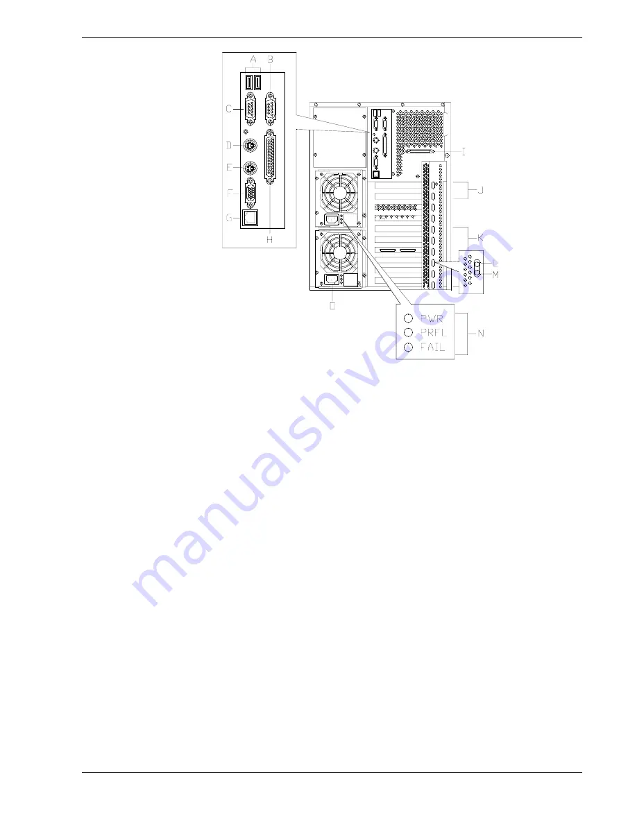
A
– USB
USB Interface connector. Appropriate driver is required.
B
– COM1
COM1 serial port 9-pin connector.
C
– COM2
COM2 serial port 9-pin connector.
D
– Keyboard
PS/2-compatible 6-pin mini-DIN connector.
E
– Mouse
PS/2-compatible 6-pin mini-DIN connector.
F
– Monitor
SVGA monitor 15-pin connector.
G
– LAN
100Base-TX/10Base-T network LAN RJ-45 connector.
H
– Printer
LPT1 25-pin parallel port connector.
I
–
External-SCSI
Wide-SCSI 68-pin connector. Connector is normally Ultra wide
SCSI having up to 4 devices connected to it. However, when a
narrow SCSI device is connected in a 5.25-inch device bay the
external SCSI devices are limited to two.
J
– PCI slots
Two 32-bit PCI connectors.
K
– Hot Plug PCI slots
Eight 64-bit Hot plug PCI connectors. Hot Plug PCI slot functionality
depends on the type of operating system support. Please note that
without PCI Hot Plug operating support you cannot replace PCI
boards while the server is turned on.
L
– PCI slot power LED
Green (steady light) when a PCI board is installed in the slot and
powered up.
M
–PCI slot attention LED
Indicates when a PCI board can be removed from its PCI slot. The
LED must be amber (flashing) and the PCI slot power LED must be
off.
N
– Power supplies
Up to three power supplies in the server chassis. Two standard
power supplies for a four CPU configuration. When an additional
power supply is installed, both the standard and additional
redundant power supplies become hot swappable. Each supply has
three status LEDs. Refer to Table 1-3 for information on power
supply status LEDs.
O
– Power connectors
There is a separate AC input power connector for each power
supply in the server chassis.
Figure 1-4.
Rear Chassis Features and Controls
Содержание Express5800/140Hb
Страница 1: ... S e r v i c e G u i d e EXPRESS5800 140Hb ...
Страница 2: ......
Страница 3: ... S e r v i c e G u i d e EXPRESS5800 140Hb ...
Страница 10: ...viii Contents ...
Страница 18: ...xvi Using This Guide ...
Страница 48: ...1 30 System Overview ...
Страница 64: ...2 16 Setting Up the System Figure 2 10 Connecting the AC Power Cord to the Server ...
Страница 98: ...3 28 Configuring Your System ...
Страница 101: ......
Страница 176: ...4 76 Disassembly and Reassembly ...
Страница 200: ...5 24 Problem Solving ...
Страница 201: ...6 Illustrated Parts Breakdown Exploded View Field Replaceable Units ...
Страница 211: ...A Technical Specifications Server Unit ...
Страница 214: ...A 4 Technical Specifications ...
Страница 220: ...B 6 Interrupt Request PCI IRQ Device I O Port Address Assignments ...
Страница 231: ...D ROMPilot BIOS Error Codes ROMPilot BIOS Error Codes ...
Страница 234: ...D 4 ROMPilot BIOS Error Codes ...
Страница 235: ...E Connectors Overview External Device Connector Pin Information ...
Страница 250: ...10 Glossary ...
Страница 256: ...Index 4 ...
Страница 257: ...xx ...
Страница 258: ... 456 01547 000 ...