


Disassembly and Reassembly 4-37
Figure 4-31. Attaching the Device Side Rails
9.
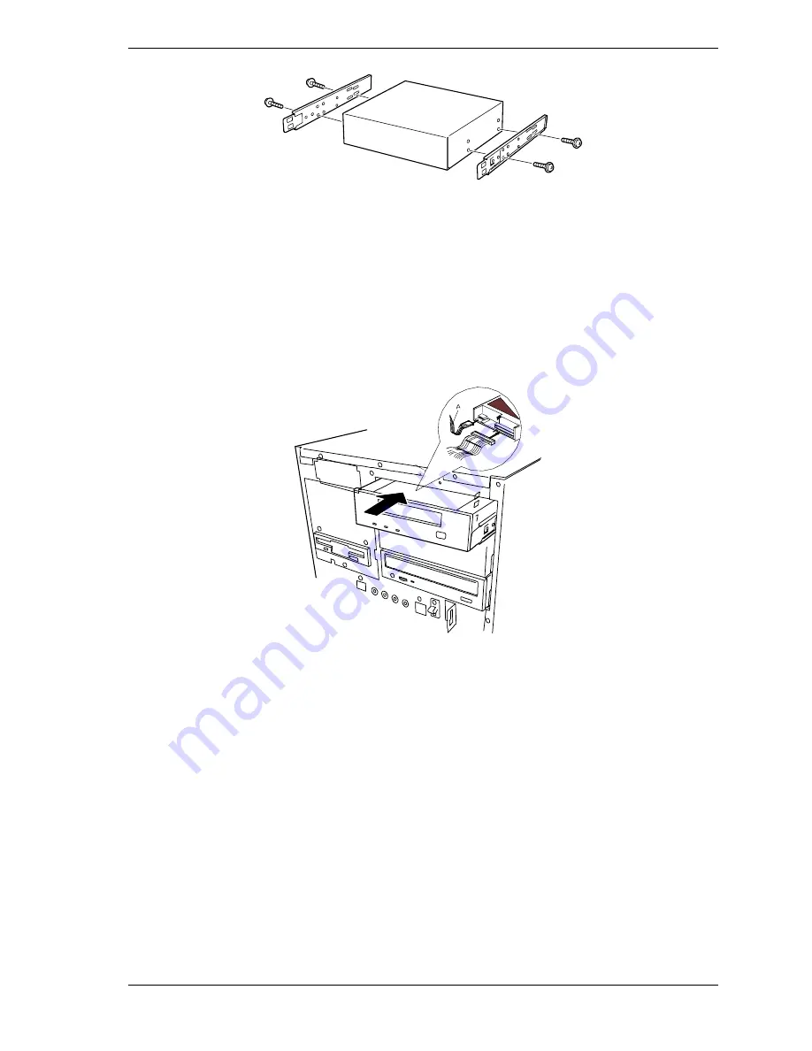
Install the media device into the bay as follows (see Figure 4-33):
!
Move any cables in the bay out of the way.
!
Align the rails on the media device with the supports in the bay.
!
Slide the device into the bay until it locks in place.
!
Connect the power cable (A) and data cable (B) to the device.
Figure 4-32. Installing a Removable Media Device
10.
If tower-based system, close the front door of the cabinet.
11.
If rack-mounted system, reinstall the rack front panel. See
Installing the
Rack-Mount Upgrade Kit
earlier in this chapter
12.
Plug in the power cords and power up the system.
13.
Run the BIOS Setup to configure the device.
Содержание Express5800/140Hb
Страница 1: ... S e r v i c e G u i d e EXPRESS5800 140Hb ...
Страница 2: ......
Страница 3: ... S e r v i c e G u i d e EXPRESS5800 140Hb ...
Страница 10: ...viii Contents ...
Страница 18: ...xvi Using This Guide ...
Страница 48: ...1 30 System Overview ...
Страница 64: ...2 16 Setting Up the System Figure 2 10 Connecting the AC Power Cord to the Server ...
Страница 98: ...3 28 Configuring Your System ...
Страница 101: ......
Страница 176: ...4 76 Disassembly and Reassembly ...
Страница 200: ...5 24 Problem Solving ...
Страница 201: ...6 Illustrated Parts Breakdown Exploded View Field Replaceable Units ...
Страница 211: ...A Technical Specifications Server Unit ...
Страница 214: ...A 4 Technical Specifications ...
Страница 220: ...B 6 Interrupt Request PCI IRQ Device I O Port Address Assignments ...
Страница 231: ...D ROMPilot BIOS Error Codes ROMPilot BIOS Error Codes ...
Страница 234: ...D 4 ROMPilot BIOS Error Codes ...
Страница 235: ...E Connectors Overview External Device Connector Pin Information ...
Страница 250: ...10 Glossary ...
Страница 256: ...Index 4 ...
Страница 257: ...xx ...
Страница 258: ... 456 01547 000 ...


