Asus AP140R-E1, User Manual
The Asus AP140R-E1 is a high-performance server rack system featuring cutting-edge technologies and superior reliability. Seamlessly manage and optimize your server's performance with our comprehensive User Manual, available for free download at manualshive.com. Explore the extensive features and maximize the potential of your Asus AP140R-E1 effortlessly.
Share
Download


Reviews:
No comments
Related manuals for AP140R-E1

AX Series
Brand: A10 Networks Pages: 17

G-DRIVE ev ATC
Brand: G-Technology Pages: 35

Sun Fire X2100 M2
Brand: Sun Microsystems Pages: 128

4-Port USB 2.0 Device Server over IP...
Brand: Quatech Pages: 2

Ultra Enterprise 3000
Brand: Sun Microsystems Pages: 48

ftServer 2500
Brand: Stratus Pages: 106

ReadyNAS Duo
Brand: Infrant Technologies Pages: 98

N3200PRO
Brand: Thecus Pages: 102

ExtremeControl IA-A-305
Brand: Extreme Networks Pages: 31

EC8200A01-E6
Brand: Extreme Networks Pages: 94

PowerEdge R6415
Brand: Dell EMC Pages: 139

t100
Brand: Atrust Pages: 21
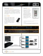
HDR44
Brand: ATON Pages: 2

ABLELink SW2001
Brand: Atop Pages: 51

ABLELink GW21 MAXI Series
Brand: Atop Pages: 110

9000 APPLIANCE SERIES
Brand: Arcserve Pages: 14

AS7110T
Brand: ASUSTOR Pages: 11

Delta
Brand: 7thSense Pages: 44


