1-6
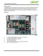
System Overview
J –
Emergency hole, CD-ROM drive
(Note that the front controls may vary
per model of CD-ROM drive.)
Insert a metallic pin (e.g., paper clip, etc.) to eject the CD
tray when the tray fails to open.
K –
SCSI hard drive bays
Each slot in a bay contains one 3.5-inch disk drive (SCSI ID:
from top to bottom 0, 1, 2, 3, and 4). Each drive has three
status LEDs. Refer to Table 1-2 for information on disk drive
status LEDs.
L –
Optional SCSI hard drive bays
Each slot in a bay contains one 3.5-inch disk drive (SCSI ID:
from top to bottom 0, 1, 2, 3, and 4). Each drive has three
status LEDs. Refer to Table 1-2 for information on disk drive
status LEDs.
M –
Activity light, diskette drive
When lit, drive is in use.
N –
Ejector button, diskette drive
Press to eject diskette.
Figure 1-3.
Front Chassis Features and Controls
Содержание Express5800/140Hb
Страница 1: ... S e r v i c e G u i d e EXPRESS5800 140Hb ...
Страница 2: ......
Страница 3: ... S e r v i c e G u i d e EXPRESS5800 140Hb ...
Страница 10: ...viii Contents ...
Страница 18: ...xvi Using This Guide ...
Страница 48: ...1 30 System Overview ...
Страница 64: ...2 16 Setting Up the System Figure 2 10 Connecting the AC Power Cord to the Server ...
Страница 98: ...3 28 Configuring Your System ...
Страница 101: ......
Страница 176: ...4 76 Disassembly and Reassembly ...
Страница 200: ...5 24 Problem Solving ...
Страница 201: ...6 Illustrated Parts Breakdown Exploded View Field Replaceable Units ...
Страница 211: ...A Technical Specifications Server Unit ...
Страница 214: ...A 4 Technical Specifications ...
Страница 220: ...B 6 Interrupt Request PCI IRQ Device I O Port Address Assignments ...
Страница 231: ...D ROMPilot BIOS Error Codes ROMPilot BIOS Error Codes ...
Страница 234: ...D 4 ROMPilot BIOS Error Codes ...
Страница 235: ...E Connectors Overview External Device Connector Pin Information ...
Страница 250: ...10 Glossary ...
Страница 256: ...Index 4 ...
Страница 257: ...xx ...
Страница 258: ... 456 01547 000 ...