


BLACK
YELLOW
MAGENTA
CYAN
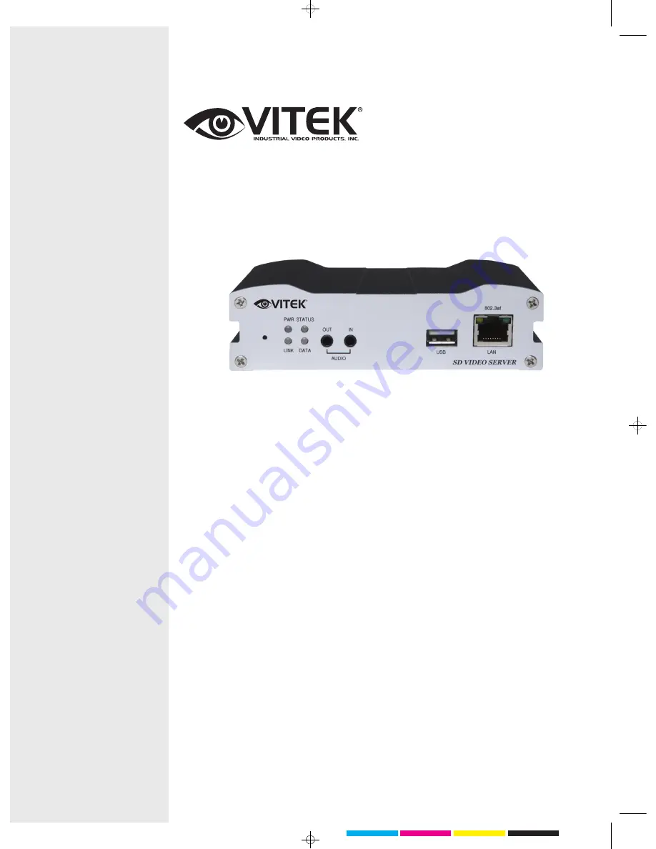
VITEK
VT-IPSD102H
Dual Streaming IP Server
with H.264 Compression
•
High quality of compression algorithm (H.264/MJPEG)
•
H.264 + H.264 / H.264 + MJPEG Dual Streaming
•
Encoder/Decoder selectable
•
Full-duplex audio/video transmission
•
30fps/25fps @ full D1 resolution
•
1:N Multi-casting and relayed data transmission
•
Protocols : TCP/IP, Multicast, HTTP, SMTP, SNMP, FTP, DHCP, DNS, Dynamic DNS,
RTP, RTSP
•
Real time monitoring/recording/playback through CMS viewer S/W and Internet
Explorer
•
Dynamic IP support with Dynamic DNS
•
Power over Ethernet(PoE) support
•
Data storage against network failure or event (USB2.0)
•
Watchdog for system recovery
•
Support for PTZ and Controller
•
Motion detection
Summary of Contents for VT-IPSD102H -
Page 21: ...VT IPSD102H Manual 20 2 2 Video Configuration ...
Page 26: ...VT IPSD102H Manual 25 2 4 Network Configuration ...
Page 29: ...VT IPSD102H Manual 28 2 5 Serial Port Configuration ...
Page 31: ...VT IPSD102H Manual 30 2 6 Event Configuration ...
Page 55: ...28492 CONSTELLATION ROAD VALENCIA CA 91355 WWW VITEKCCTV COM 888 VITEK 70 ...


