


1. Installing Internal Optional Devices
Express5800/T110j User’s Guide
41
Chapter 2 Preparations
Removal
Remove a DIMM in the following procedure.
Note
When removing a defective DIMM, check error messages displayed at POST or
NEC ESMPRO and check the DIMM slot where the defective DIMM is installed.
At least one DIMM needs to be installed for the server to operate.
1.
See steps 1 to 4 in
Chapter 2 (1.2 Overview of Installation and Removal)
for preparations.
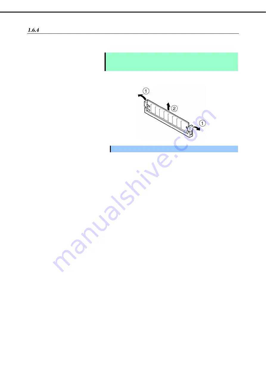
2.
Open both levers of the target DIMM slot
outward.
The DIMM is unlocked
3.
Remove the DIMM by pulling it out from
the slot in a straight direction.
Important Do not apply too much pressure when you pull a DIMM out from the socket.
4.
Assemble the server.
5.
Turn on the server and confirm that no error messages are displayed on POST. If any error message
is displayed, see
Chapter 3 (1. Post Error Message)
in "
Maintenance Guide
".
6.
Set the paging file size to the recommended value (Total memory size x 1.5) or more.
When using a Windows OS, see
Chapter 1 (5.1 Specifying Memory Dump Settings (Debug
Information))
in "
Installation Guide (Windows)
".
For other OS, see the manual provided with the operating system or contact your sales
representative.
Содержание EXP339
Страница 127: ...MEMO...


