Option Installation 3-7
Expansion Board Installation
Install expansion boards in the system as follows.
1.
Remove the access cover.
2.
Follow any preinstallation instructions that come with the expansion board (such
as setting switches or jumpers on the board).
3.
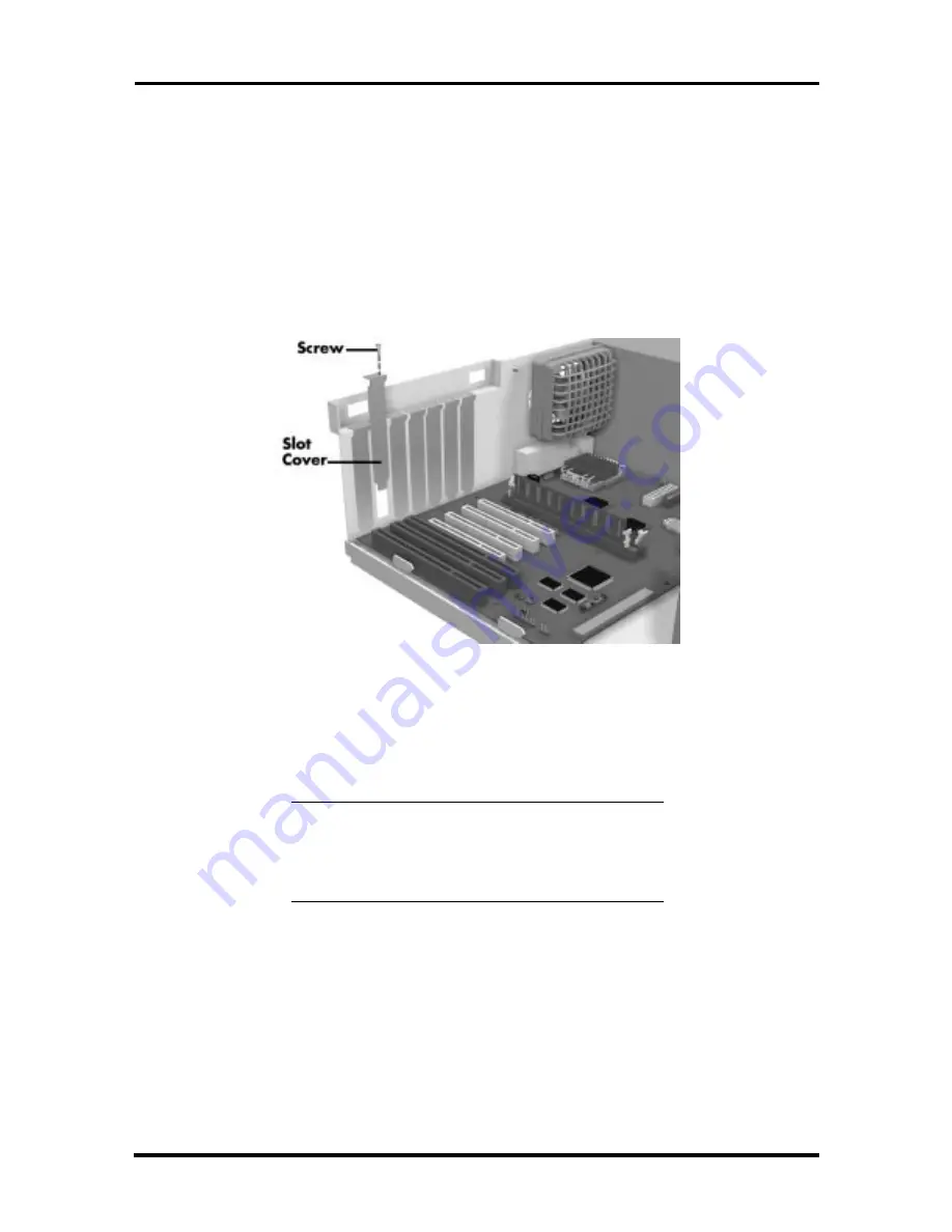
Remove the screw securing an expansion slot cover and remove the cover.
Figure 3-5 Removing the Slot Cover
Save the screw for installing the expansion board. Be sure to save the slot cover
for future use.
CAUTION:
A slot cover can damage the system
board or any option board if it falls into the
system. Take care to keep the slot cover from
falling when removing the screw.
If the slot cover does fall into the unit, remove it before replacing the cover.
4.
Hold the board by its edges and insert it into the expansion slot.
5.
Press the board firmly into the expansion slot connector. Gently rock the board
from side-to-side to seat it into the connector.
6.
Insert the screw removed earlier to secure the expansion board to the support
bracket.
7.
Attach any cables required by the expansion board.
Содержание Direction T-Series
Страница 8: ...Contents ix...
Страница 12: ...Abbreviations xiii VFC VESA compliant feature connector VGA Video Graphics Array VRAM video RAM W watt W write...
Страница 63: ...3 26 Option Installation 5 Turn on the printer and the computer Figure 3 20 Locating the Parallel Port...
Страница 101: ...B 2 Connector Pin Assignments Figure B 1 System Board Connectors and Slots Figure B 2 System Board External Connectors...


