78K0/Fx2 – CAN it!
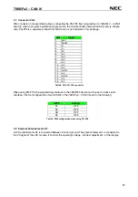
3.7 Connector CN4
CN4 connector (not assembled) allows connecting the PG-FP4 flash programmer to
78K0/Fx2 – CAN it!
board in order to program application programs into the microcontroller internal FLASH memory. Please
note, PG-FP4 is a separate product from NEC and it is not included in this package.
CN4
Signal
1
GND
2
RESET
3
SI
4
V
CC
5
SO
6
N.C.
7
SCK
8
N.C.
9
N.C.
10
N.C.
11
N.C.
12
FLMD1
13
N.C.
14
FLMD0
15
N.C.
16
N.C.
Table 8: CN4, PG-FP4 connector
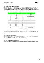
When using PG-FP4, the programming interface to the 78K0/FF2 device must be set to clock serial
interface, CSI. Set configuration of switch SW4 of the
78K0/Fx2 – CAN it!
board to the following:
SW4
Setting
S1 OFF
S2 OFF
S3 OFF
S4 OFF
Table 9: SW4 configuration when using PG-FP4
3.8 External Potentiometer R7
A 47K potentiometer R7 is connected between Vcc and ground. The potentiometer arm is connected to
the V0 signal of the LCD module. It controls the operating voltage - contrast adjustment - of the display.
17
Содержание 78K0/Fx2
Страница 80: ...78K0 Fx2 CAN it 15 USB interface cable Mini B type Figure 77 USB interface cable Mini B type 80 ...
Страница 81: ...78K0 Fx2 CAN it 16 Schematics Figure 78 78K0 Fx2 CAN it baseboard schematics 81 ...
Страница 82: ...78K0 Fx2 CAN it Figure 79 78K0 Fx2 CAN it CPU module schematics 82 ...
Страница 83: ...78K0 Fx2 CAN it MEMO 83 ...


