78K0/Fx2 – CAN it!
12. IAR configuration for On-Board debugging
12.1 Setup COM port for IAR C-SPY debugger
Before using the On-Board debug function of the
78K0/Fx2 – CAN it!
board together with the IAR C-SPY
debugger it is necessary to set the corresponding USB serial COM port of the host computer. Just be sure
that you have installed the USB driver first.
To set the COM port, please execute the registry script file “
FTDI_Set_Registry.reg”
. The script file can be
found in the typical installation path of the IAR Embedded Workbench, i.e.:
“C:\Program Files\IAR System\Embedded Workbench 4.0\78k\config\nec”
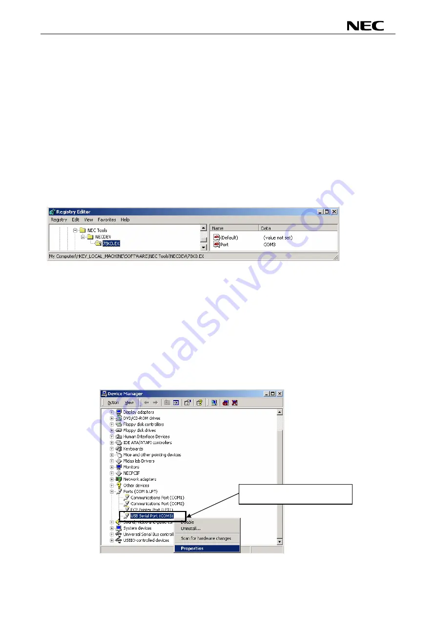
This script file will set the COM port number in the following registry key:
[HKEY_LOCAL_MACHINE\SOFTWARE\NEC Tools\NECDEV\78K0.EX]
Figure 65: Registry entry for IAR C-SPY debugger COM port setting
As default the serial port COM3 is set in the script file. If the
78K0/Fx2 – CAN it!
board is used on a different
USB serial COM port, please edit the script file accordingly. To do so, open the script file with your preferred
editor i.e. “NOTEPAD” and make changes as described in the file. Then run the script file.
12.2 Configuration of USB serial COM port
To optimize the communication between the IAR C-SPY debugger and the
78K0/Fx2 – CAN it!
board the
USB serial COM port must be configured. To do so, open the “Device Manager”, which can be found in
properties of “My Computer”. Then locate the USB serial COM port and select “Properties”, as show in figure
below:
Locate the "USB Serial Port
(COM?)" and select properties.
Figure 66: Configuration of COM port for IAR C-SPY debugger 1/4
69
Содержание 78K0/Fx2
Страница 80: ...78K0 Fx2 CAN it 15 USB interface cable Mini B type Figure 77 USB interface cable Mini B type 80 ...
Страница 81: ...78K0 Fx2 CAN it 16 Schematics Figure 78 78K0 Fx2 CAN it baseboard schematics 81 ...
Страница 82: ...78K0 Fx2 CAN it Figure 79 78K0 Fx2 CAN it CPU module schematics 82 ...
Страница 83: ...78K0 Fx2 CAN it MEMO 83 ...


