background image


www.neatech.it 

2/122 

2


PREPARATION FOR FIRST USE 

2.1


Checks to be made on delivery 


Check for the integrity of the original packaging. 


Check for any anomalies on shipping documents. 


Check for the functionality and integrity of the device in all its parts, at the time of delivery 

or immediately thereafter, to ensure that no damage has resulted from a careless transport. 


Make sure the surface of the device is not damaged, scratched, bent, etc. 


Any fault or damage found must be immediately reported on the shipping documents and 

promptly communicated to the shipper.  

2.2


Unpacking 

Inside the box there are:  


Evo3 wheelchair 


Documents and manual  


Charger  


The  wheelchair  is  delivered  already  mounted  and  ready  to  use.  Before  starting  to  use  the 
wheelchair please check if all described components are present.

 If not, please contact as soon 

as possible the vendor.


PACKAGING DISPOSAL 

To properly recycle the packaging materials follow instructions provided 

by your local waste disposal service.  


Содержание EVO3

Страница 1: ...USER MANUAL 2019 01...

Страница 2: ......

Страница 3: ...names EVO 3 EVO3 FWD EVO3 RWD EVO 3 FWD EVO 3 RWD satisfies the requirements laid down by the European Directive 93 42 according to the criteria for classification of Annex IX of this Directive it is...

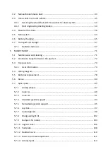
Страница 4: ...sition Version with biomechanical movements 15 3 7 1 Standard support Depth 15 3 7 2 Retractable support S045 V263 Depth 16 3 8 Seat depth Version without biomechanical movements 17 3 9 Backrest angle...

Страница 5: ...71 5 2 Controls to be performed on the product 72 5 3 Tire puncture 73 5 3 1 User information 73 5 4 Wiring diagram 77 5 5 Batteries replacement 78 5 6 Reuse 84 5 7 Spare parts 85 5 7 1 Antitip wheels...

Страница 6: ...ATIONS 117 6 1 Maximum user weight 118 6 2 Other provided information 119 6 3 Dimensions 120 6 3 1 Version with biomechanical movements 120 6 3 2 Version with biomechanical movements 121 7 Warranty te...

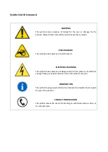
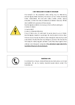
Страница 7: ...nce of pinch hazard ELECTRICAL WARNING This symbol means presence of danger related to the presence of electrical energy Please pay special attention when this symbol is present INFORMATION This symbo...

Страница 8: ...t on armrests ANTI TIP DEVICES Using anti tippers substantially reduces your risk of falling over which can cause serious injury The Anti Tippers will keep you from falling over but they will limit yo...

Страница 9: ...nintended directions If any of these occur it could result in severe injury to you or others Electromagnetic radiation can damage the control system of your chair There is no way to know the effect on...

Страница 10: ...nse in order to preserve his own safety The manufacturer declines all responsibility for any accidents occurring during the working with the product WARNING It is prohibited to use the product or its...

Страница 11: ...ories or spare parts on the product Do not use the product in combination with other medical devices without first having considered any risk due to combination of more products MANUFACTURER For any n...

Страница 12: ...r high engineering which allows it to offer a broader spectrum of choices than in the past it is a quality product that features an elegant design and performance Total length Total width Seat height...

Страница 13: ...of the device is not damaged scratched bent etc Any fault or damage found must be immediately reported on the shipping documents and promptly communicated to the shipper 2 2 Unpacking Inside the box t...

Страница 14: ...air is required please contact the manufacturer to have instructions and the most suitable version of the software In case of problems with this part of the software please contact the manufacturer So...

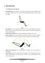
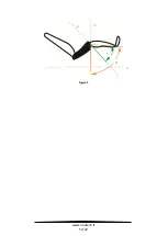
Страница 15: ...al and negative when the seat is tilted forward Absolute backrest angle D this is the angle between the backrest and the seat Backrest angle E this is the angle between the backrest and the chassis of...

Страница 16: ...www neatech it 5 122 Figure 3 g F H m a...

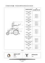
Страница 17: ...by an authorized service center Table 1 3 2 1 Version of the wheelchair with biomechanics movements Adjustment Section Type of operation Seat depth Service Manual C Service Armrests height 3 3 B Assis...

Страница 18: ...ion Type of operation Seat depth 3 8 B Assistant Backrest angle 3 9 B Assistant Armrests depth 3 10 B Assistant Armrests height 3 11 B Assistant Sidepad height 3 12 B Assistant Footplates height 3 13...

Страница 19: ...GE It is not easy to provide a range for this adjustment because there are too many configuration and possibilities Average needed time 5 min Difficulty level Easy WARNING As this adjustment is carrie...

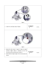
Страница 20: ...in figure ALLEN WRENCH 5 mm Figure 5 Adjust the bolt shown in figure in order to adjust armrests height Rotate it clockwise to rise the armrest and counterclockwise to lower it When finished tighten...

Страница 21: ...s RANGE It is not easy to provide a range for this adjustment because there are too many configuration and possibilities Average needed time 5 min Difficulty level Easy RIGHT AND LEFT SIDE It is possi...

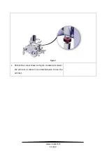
Страница 22: ...www neatech it 11 122 Figure 7 Rotate the screw shown in figure clockwise to lower the armrest or rotate it counterclockwise to rise the armrest...

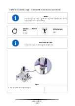
Страница 23: ...movements A POSSIBLE VALUES 12 24 36 Average needed time 5 min Difficulty level Easy RIGHT AND LEFT SIDE It is possible to adjust separately left and right side Figure 8 Unscrew the screw shown in fig...

Страница 24: ...0 cm 55 0 cm M2 P2 S042 V380 M2 P2 S042 V389 45 0 cm 49 0 cm 53 0 cm 57 0 cm M3 P1 S042 V381 M4 P2 S042 V384 M3 P1 S042 V390 M4 P2 S042 V393 51 0 cm 55 0 cm 59 0 cm 63 0 cm M3 P2 S042 V382 M4 P3 S042...

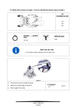
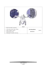
Страница 25: ...neatech it 14 122 Figure 9 Remove the backrest upholstery Unscrew the 4 screws shown in figure Adjust the height as desired Screw again the screws Mount again the backrest upholstery OPEN END WRENCH 8...

Страница 26: ...sy to provide a range for this because there are too many configuration and possibilities Average needed time 5 min Difficulty level Easy 3 7 1 Standard support Depth Figure 10 Unscrew the 2 screws sh...

Страница 27: ...st the angle of the joystick simply acting on the two levers shown in figure Figure 11 3 7 2 Retractable support S045 V263 Depth Figure 12 Unscrew the 2 screws shown in figure Adjust the depth and the...

Страница 28: ...MAX VALUE M1 S042 V073 300 mm 420 mm M2 S042 V074 300 mm 460 mm M3 S042 V075 300 mm 485 mm 485 mm 500 mm M4 S042 V071 30 0 mm 485 mcm 485 mm 520 mm Table 5 WARNING It is needed to set separately left...

Страница 29: ...atech it 18 122 Figure 13 Remove the backrest Loosen the 6 screws shown in figure Set the backrest according to the desired seat depth Tight again the 6 screws Mount again the backrest OPEN END WRENCH...

Страница 30: ...00 or 105 105 or 1110 110 or 115 115 or 120 Angle adjustable with pistons 90 95 95 100 100 105 105 110 110 115 120 125 WARNING It is needed to set separately left and right backrest angle Always set t...

Страница 31: ...re Set the position of the hardware highlighted in figure according to the desired backrest angle Screw again screws OPEN END WRENCH 10 mm ADDITIONAL ADJUSTMENT After adjusted the angle of backrest as...

Страница 32: ...a range for adjustment of armrests depth because there are too many configuration and possibilities RIGHT AND LEFT SIDE It is possible to adjust separately left and right armrest Average needed time...

Страница 33: ...ure 17 Loosen the lever shown in figure and remove the armrest Figure 18 Loosen the 2 screws shown in figure and set the depth of armrest clamp as desired Tighten again the 2 screws and put back the a...

Страница 34: ...www neatech it 23 122 ADDITIONA ADJUSTMENT Moreover it is possible to adjust armrest depth unscrewing the 2 screws shown in figure with a 4 mm allen wrench Figure 19...

Страница 35: ...MIN VALUE A MAX VALUE 230 mm 300 mm RIGHT AND LEFT SIDE It is possible to adjust separately left and right armrest Average needed time 5 min Difficulty level Easy SIDEPAD JOYSTICK AND ARMREST HEIGHT...

Страница 36: ...www neatech it 25 122 Figure 20 Loosen the 2 screws shown in figure Set the armrest according to the desired height Tight again the 2 screws ALLEN WRENCH 4 mm...

Страница 37: ...adjustment of sidepad because there are too many configuration and possibilities RIGHT AND LEFT SIDE It is possible to adjust separately left and right sidepad SIDEPAD JOYSTICK AND ARMREST HEIGHT It i...

Страница 38: ...E Please be sure that the chosen position doesn t represent an obstacle for armrest Figure 21 Figure 22 Unscrew the 2 screws shown in figure and set the position of sidepad as desired Screw again the...

Страница 39: ...0 cm 17 5 cm 20 0 cm 22 5 cm 25 0 cm 27 5 cm 30 0 cm 32 5 cm 35 0 cm 37 5 cm 40 0 cm Angle adjustable 15 0 cm 17 5 cm 20 0 cm 22 5 cm 25 0 cm 27 5 cm 30 0 cm 32 5 cm 35 0 cm 37 5 cm RIGHT AND LEFT SID...

Страница 40: ...e 6 mm allen wrench while holding the nut behind with the 13 mm open end wrench Repeat the operation for both left and right side of the wheelchair Set the position of the footplate according to desir...

Страница 41: ...e a range for adjustment of footrests because there are too many configuration and possibilities In any case it is always possible to choose between 3 different depth RIGHT AND LEFT SIDE It is possibl...

Страница 42: ...of the footplate according to desired angle Tighten again the screws Tighten again the screws ALLEN WRENCH 4 mm Depth adjustment Figure 25 Unscrew the 2 screws shown in figure Set the position of the...

Страница 43: ...de a range for this because there are too many configuration and possibilities Average needed time 5 min Difficulty level Easy 3 15 1 Standard support Depth and height Figure 26 Unscrew the 2 screws s...

Страница 44: ...t the angle of the joystick simply acting on the two levers shown in figure Figure 27 3 15 1 Retractable support Depth and height Figure 28 Unscrew the 2 screws shown in figure Adjust the depth and th...

Страница 45: ...sition Default position means that all adjustable parts of the wheelchair are set in the most stable and safe configuration ADJUSTABLE PARTS VALUE NOTES Seat angle 0 Backrest angle 90 Legrest angle 90...

Страница 46: ...transfer distance Also be certain the wheel locks are engaged to prevent the wheels from moving Do not let children use the wheelchair without supervision INFORMATION The product is not intended to b...

Страница 47: ...of the age of the passenger The wheelchair is not designed for weight training and is unsafe for use as a seat while weight training Do not lean over the top of the back upholstery to reach objects f...

Страница 48: ...set the seating system to default position It is better to use a drive profile with low speed Figure 29 Dealing with downhill When facing a downhill road it is recommended to set the seating system to...

Страница 49: ...Don t use the wheelchair down or up a hazardous incline if the surface is covered with snow ice or the surface is uneven WARNING The stopping distance on slopes can be significantly greater than on l...

Страница 50: ...rk environments Don t use the wheelchair in dark environments without lights turned on Pelvic belt The wheelchair has the predisposition for a pelvic belt Pelvic belt is only design to position the us...

Страница 51: ...e wheelchair with a user on board Do not lift the wheelchair grabbing the legrests If you really need to lift the wheelchair it is suggested to grab it with the help of at least one other people Grab...

Страница 52: ...ion to navigate all working mode of the wheelchair For example it is possible to choose between drive and seat function PROFILE As default in the wheelchair they are saved some different drive profile...

Страница 53: ...TION Set time Use this function to set the time shown on the display Distance Use this function to see total and partial distance made with the wheelchair It is also possible to reset partial distance...

Страница 54: ...rn off the wheelchair Then you can act on the release lever shown in Figure When the brakes are released it is not possible to drive the wheelchair Figure 35 UNLOCKED LOCKED LOCKED UNLOCKED WARNING Wh...

Страница 55: ...neatech it 44 122 WARNING The drive system should be re engaged before an occupant is left unattended or attempts to operate the wheelchair WARNING Always act on both left and right manual release lev...

Страница 56: ...bility to a forward facing position Always use ISO 10542 1 approved Wheelchair Tiedown and Occupant Restraint Systems which are suitable for the weight of the wheelchair or Dahl docking Wheelchair use...

Страница 57: ...AS ARMRESTS OR WHEELS PROPER BELT RESTRAINT FIT BELT RESTRAINTS SHOULD MAKE FULL CONTACT WITH THE SHOULDER CHEST AND PELVIS AND PELVIC BELTS SHOULD BE POSITIONED LOW ON THE PELVIS NEAR THE THIGH ABDO...

Страница 58: ...ench Repeat operation for both left and right side of the wheelchair ALLEN WRENCH 5 mm Figure 39 Moreover chest belt must be fixed in the upper part of the backrest Firstly mount the fixing plate as s...

Страница 59: ...nstructions in the manual are followed Particularly it may exist some options or accessories that are not compatible with the use of the wheelchair as a seat in a motor vehicle or it may exist some ac...

Страница 60: ...with the ATD restrained by both pelvic and shoulder belts WARNING Both pelvic and shoulder belt should be used to reduce the possibility of head and chest impacts with vehicle components WARNING In o...

Страница 61: ...ents specified in ISO 7176 19 2008 WARNING The wheelchair should be inspected by a manufacturer s representative before reuse following involvement in any type of vehicle collision WARNING Alterations...

Страница 62: ...neatech it 51 122 WARNING Care should be taken when applying the occupant restraint to position the seatbelt buckle so that the release button will not be contacted by wheelchair components during a c...

Страница 63: ...ts marked with the symbol shown in figure Figure 41 Use the tie down points marked with the symbol shown in figure Hook the wheelchair in 4 points two in the front part and two in the rear part Figure...

Страница 64: ...s should form angles shown below PREFERRED ANGLES OF FRONT WHEELCHAIR TIE DOWN STRAPS Figure 43 PREFERRED ANGLES OF REAR WHEELCHAIR TIE DOWN STRAPS Figure 44 WARNING Always use four tie down straps 40...

Страница 65: ...ht up until the lock plate is either fully engaged or else the wheelchair is removed from the docking station As an indication that the wheelchair is properly secured the warning tone will cease the r...

Страница 66: ...lock mechanisme which makes it impossible to reverse If this happens repeat above ulocking procedure Figure 46 CONTACT INFORMATION For more information contact the manufacturer of the wheelchair or th...

Страница 67: ...the desired function move the joystick left or right The number and the type of available function may change according to the specific customization of each wheelchair MOVE UP Move the joystick forwa...

Страница 68: ...s possible to lower legrest The movement stops before the legrest crashes into the chassis In any case an authorized service center is able to choose the angle where the movement stops When the moveme...

Страница 69: ...wo different actuators at the same time it is needed a sophisticated software to adjust the speed of these two actuators This software can be fine tuned by an authorized service center during the set...

Страница 70: ...nt to not use the legrest function on a non flat surface or near steps or obstacles AXIS 5 REHAB Figure 51 Figure 52 Figure 53 MOVE UP The wheelchair will go in lay down position and then in the posit...

Страница 71: ...eelchair will go automatically into the position shown in Figure 54 An authorized service center is able to adjust the angles shown in figure When the movement stops you will hear a sound MOVE DOWN it...

Страница 72: ...hair will go automatically into the position shown in Figure 56 An authorized service center is able to adjust the angles shown in figure When the movement stops you will hear a sound MOVE DOWN it is...

Страница 73: ...ir will go automatically into the position shown in Figure 58 An authorized service center is able to adjust the angles shown in figure When the movement stops you will hear a sound MOVE DOWN it is po...

Страница 74: ...cuit OFF ON Figure 60 Figure is taken having the wheelchair on the front and shows the position ON and OFF of the switch If the power chair suddenly stops use the switch to connect again batteries to...

Страница 75: ...www neatech it 64 122 If the switch operates often this means that there is a major electrical fault The cause of fault should be checked carefully For more information please contact the manufacturer...

Страница 76: ...ct CHARGER SPECIFICATION 24 V MIN 6 A MAX 10 A Charge profile for AGM batteries Connect the power cord to a power supply 230 V Connect the cable to the joystick as shown in Figure RNET Figure 61 When...

Страница 77: ...uch as remaining battery power battery state of aging and temperature However the approximate charging time is about 12 hours Battery charging should be done in well ventilated environments Never char...

Страница 78: ...ion follow these instructions It is possible to store the wheelchair in a place with a temperature between 20 C and 45 C Turn off the wheelchair Turn off the main switch See section 4 5 WARNING If you...

Страница 79: ...igure 63 Unplug the connectors shown in figure Figure 64 Unscrew the 4 screws shown in figure Remove the metalsheet with mounted modules It is not necessary to unplug any wires Pull away the batteries...

Страница 80: ...69 122 Figure 65 Unscrew the 4 screws shown in figure WARNING Batteries are mounted in a metal enclosure Total weight is about 40 kg Please do not remove batteries from their enclosure Please pay spe...

Страница 81: ...transported in the storage compartment of the vehicle even without any package The unoccupied wheelchair can be also shipped via air If it is necessary to ship the wheelchair it is very important to p...

Страница 82: ...void prolonged contact of the wheelchair with water It may cause oxidation of the metal parts Avoid long exposure of the wheelchair to direct sunlight WARNING Any work on the wheelchair must be perfor...

Страница 83: ...on 4 2 Before each use B Assistant Check that no wires are in the way for the movements of the chair Before each use B Assistant Check the charge of batteries Daily A User Clean the wheelchair Weekly...

Страница 84: ...www neatech it 73 122 5 3 Tire puncture 5 3 1 User information Traction wheels Figure 67 Lift the wheelchair Unscrew the 4 screws shown in figure Remove the wheel ALLEN WRENCH 6 mm...

Страница 85: ...me time two allen wrenches Remove the castor ALLEN WRENCH 5 mm ALLEN WRENCH 5 mm Contact an authorized service center for the repair or the substitution of the damaged wheel When the authorized servic...

Страница 86: ...tech it 75 122 INFORMATION With wheels 320 S042 V620 it is necessary to mount the screws of the castor in holes A With wheels 3 00 8 it is necessary to mount the screws of the castor in holes B Figure...

Страница 87: ...ray 320x58 mm B R042 0121B Tire of traction wheel black 320x58 mm B R042 0121C Tire of traction wheel gray 360x80 mm B R042 0121D Tire of traction wheel black 360x80 mm B R042 0122A Tube of traction w...

Страница 88: ...www neatech it 77 122 5 4 Wiring diagram Figure 70...

Страница 89: ...www neatech it 78 122 5 5 Batteries replacement Figure 71 Unscrew the 4 screws shown in figure Remove the cover ALLEN WRENCH 3 mm...

Страница 90: ...igure 72 Unplug the connectors shown in figure Figure 73 Unscrew the 4 screws shown in figure Remove the metalsheet with mounted modules It is not necessary to unplug any wires Pull away the batteries...

Страница 91: ...www neatech it 80 122 Figure 74 Pull away batteries WARNING Batteries are mounted in a metal enclosure Total weight is about 40 kg Please do not remove batteries from their enclosure...

Страница 92: ...www neatech it 81 122 Figure 75 Unscrew the 4 screws shown in figure Remove the metallic handle ALLEN WRENCH 3 mm...

Страница 93: ...atech it 82 122 Figure 76 Remove cables from the batteries Mount new batteries following instructions in reverse order ALLEN WRENCH 5 mm WARNING Each battery weights about 18 kg Please pay special att...

Страница 94: ...sheets useful to reduce short circuit risk When placing back batteries please be sure that they are correctly fixed in their proper place Figure 77 BATTERIES SPECIFICATION 2 x 12 V 50 Ah GEL Type MAX...

Страница 95: ...Before dispensing it the product must be cleaned and subjected to maintenance The operating instructions are included in this manual and must also be provided when the product is passed on WARNING Thi...

Страница 96: ...for castor B R042 0133 Tube for castor B R042 0134 Fork with dump B R042 0135 Bearings B R042 0136 Spring kit for castor B R042 0140 Antitip wheel A R042 0150 Cover A A R042 0160 Cover B A R042 0170...

Страница 97: ...B R042 0360 Backrest actuator A R042 0371 Backrest cover A R042 0372 Ruler for armrest adjustment B R042 0373 Joint for armrest A R042 0380 Armrest A R042 0390 Connector and sensor board B Table 10 S...

Страница 98: ...Antitip wheels Average needed time 5 min Difficulty level Easy Figure 78 Unscrew the screws shown in figure Substitute the wheel Screw the new screws Repeat operations for both left and right side of...

Страница 99: ...www neatech it 88 122 Code Description Type of operation Notes R042 0140 Antitip wheel A Figure 79 Code ID Quantity R042 0140 1 1 R042 0140 2 2...

Страница 100: ...afety perform this operation it is necessary to activate some powered seat functions In case of problems with the seating system please contact the manufacturer Figure 80 Lift the seat and raise legre...

Страница 101: ...www neatech it 90 122 Code Description Type of operation Notes R042 0150 Cover A A Figure 81 Code ID Quantity R042 0150 172 1 R042 0150 371 4...

Страница 102: ...www neatech it 91 122 5 7 3 Cover B Average needed time 5 min Difficulty level Easy Figure 82 Unscrew the screws shown in figure Substitute the cover Screw the new screws ALLEN WRENCH 3 mm...

Страница 103: ...www neatech it 92 122 Code Description Type of operation Notes R042 0160 Cover B A Figure 83 Code ID Quantity R042 0160 382 1 R042 0160 383 4...

Страница 104: ...evel Easy Figure 84 Unscrew the 2 screws shown in figure Remove the joystick ALLEN WRENCH 4 mm Figure 85 Unscrew the 2 screws shown in figure Unscrew the 2 screws shown in figure Substitute the joysti...

Страница 105: ...R042 0190A Standard joystick support A Figure 86 Code ID Quantity R042 0190 A 76 1 R042 0190 A 107 2 R042 0190 A 114 2 R042 0190 A 336 1 R042 0190 A 337 1 R042 0190 A 338 1 R042 0190 A 339 1 R042 0190...

Страница 106: ...e 5 min Difficulty level Easy Figure 87 Unscrew the 2 screws shown in figure Remove the joystick ALLEN WRENCH 3 mm Figure 88 Unscrew the 2 screws shown in figure Substitute the joystick support Mount...

Страница 107: ...de Description Type of operation Notes R042 0190B Retractable joystick support A Figure 89 Code ID Quantity R042 0190B 63 1 R042 0190B 64 1 R042 0190B 65 4 R042 0190B 107 2 R042 0190B 114 2 R042 0190B...

Страница 108: ...asy Standard joystick support Figure 90 Unscrew the 2 screws shown in figure Substitute the joystick ALLEN WRENCH 4 mm Retractable joystick support Figure 91 Unscrew the 2 screws shown in figure Unscr...

Страница 109: ...www neatech it 98 122 Code Description Type of operation Notes R042 0200 Standard joystick support Joystick A Figure 92 Code ID Quantity R042 0200 91 1...

Страница 110: ...7 Castor light kit Average needed time 10 min Difficulty level Easy Figure 93 Unscrew the screws shown in figure If desired substitute the cover ALLEN WRENCH 3 mm Figure 94 Unscrew the glass shown in...

Страница 111: ...gure 95 Unscrew the screw shown in figure Substitute the parts shown in figure ALLEN WRENCH 3 mm Code Description Type of operation Notes R042 0250 Kit light for castor A R042 0251 Light for castor A...

Страница 112: ...eatech it 101 122 Figure 96 Code ID Quantity R042 0250 162 1 R042 0250 288 1 R042 0250 291 1 R042 0250 305 1 R042 0250 308 1 R042 0250 429 1 R042 0250 704 3 R042 0250 708 2 R042 0521 162 1 R042 0252 3...

Страница 113: ...Mudguard light kit Average needed time 10 min Difficulty level Easy Figure 97 Unscrew the glass shown in figure Unplug the light Figure 98 Unscrew the screw shown in figure Substitute the parts shown...

Страница 114: ...ion Notes R042 0270B Mudguard kit RH A R042 0270A Mudguard kit LH A R042 0271 Light for mudguard A Figure 99 Code ID Quantity R042 0270 164 1 R042 0270 309 1 R042 0270 312 1 R042 0270 315 1 R042 0270...

Страница 115: ...rs Average needed time 10 min Difficulty level Easy Figure 100 Unscrew the screws shown in figure Substitute the bumper for motor Substitute the bumper for motor Repeat operations for both left and ri...

Страница 116: ...www neatech it 105 122 Code Description Type of operation Notes R042 0280 Bumpers for motors B Figure 101 Code ID Quantity R042 0280 181 2 R042 0280 374 4 4 1 1...

Страница 117: ...www neatech it 106 122 5 7 10 Legrest cover Average needed time 5 min Difficulty level Easy Figure 102 Remove the seeger shown in figure Use a screwdriver as a lever Substitute the cover SCREWDRIVER...

Страница 118: ...www neatech it 107 122 Code Description Type of operation Notes R042 0311 Legrest cover A Figure 103 Code ID Quantity R042 0311 320 1 R042 0311 363 2...

Страница 119: ...www neatech it 108 122 5 7 11 Footplate Average needed time 5 min Difficulty level Easy Figure 104 Remove seeger shown in figure Use a screwdriver as a lever Substitute footplate SCREWDRIVER...

Страница 120: ...www neatech it 109 122 Code Description Type of operation Notes R042 0320 Footrest A Figure 105 Code ID Quantity R042 0320 316 1 R042 0320 363 2...

Страница 121: ...12 Backrest cover Average needed time 5 min Difficulty level Easy Figure 106 Substitute the cover shown in figure Code Description Type of operation Notes R042 0371 Backrest cover A Figure 107 Code I...

Страница 122: ...t 111 122 5 7 13 Ruler for armrest adjustment Average needed time 10 min Difficulty level Easy Figure 108 Unscrew the screw shown in figure ALLEN WRENCH 4 mm Figure 109 Unscrew the part shown in figur...

Страница 123: ...hown in figure Code Description Type of operation Notes R042 0372 Ruler for armrest adjustment B Figure 111 Code ID Quantity R042 0372 309 1 R042 0372 310 1 R042 0372 311 1 R042 0372 312 1 R042 0372 3...

Страница 124: ...2 5 7 14 Armrest joint Average needed time 10 min Difficulty level Easy Figure 112 Loosen the 2 screws shown in figure Substitute the armrest ALLEN WRENCH 5 mm Code Description Type of operation Notes...

Страница 125: ...2 Figure 113 Code ID Quantity R042 0373 292 1 R042 0372 294 2 R042 0372 295 1 R042 0372 301 1 R042 0372 302 1 R042 0372 303 1 R042 0372 355 1 R042 0372 357 2 R042 0372 371 1 R042 0372 374 2 R042 0372...

Страница 126: ...www neatech it 115 122 5 7 15 Armrest Average needed time 5 min Difficulty level Easy Figure 114 Loosen the 2 screws shown in figure Remove the armrest ALLEN WRENCH 5 mm...

Страница 127: ...www neatech it 116 122 Code Description Type of operation Notes R042 0380 Armrest A Figure 115 Code ID Quantity R042 0380 298 1 R042 0380 300 1 R042 0380 375 3...

Страница 128: ...7 EN 12184 2009 ISO 7176 8 Intended use The Evo3 wheelchair is intended to be used by those groups of users with temporary or permanent mobility difficulties confined to a sitting position who need to...

Страница 129: ...www neatech it 118 122 6 1 Maximum user weight Seat width MAX 30 cm 50 kg 34 cm 80 kg 38 cm 80 kg 42 cm 80 kg Table 11...

Страница 130: ...on of the wheelchair MAX 125 kg Dynamic stability 6 Static stability downhill 9 Static stability uphill 9 Static stability sideways 9 Seat plane angle 45 Effective seat depth MIN 30 0 cm MAX 52 0 cm E...

Страница 131: ...mensions 6 3 1 Version with biomechanical movements A 300 mm 340 mm 380 mm 420 mm B 560 mm C 495 mm 535 mm 575 mm 615 mm G MIN 270 mm MAX 480 mm H Wheels 320 46 0 cm Wheels 3 00 8 48 0 cm J FWD 945 mm...

Страница 132: ...40 mm 380 mm 420 mm B 560 mm C 495 mm 535 mm 575 mm 615 mm D MIN 300 mm MAX 420 mm MIN 300 mm MAX 460 mm MIN 300 mm MAX 500 mm MIN 300 mm MAX 520 mm E 230 mm 300 mm G MIN 150 mm MAX 480 mm H Wheels 32...

Страница 133: ...r workmanship The warranty doesn t cover parts subject to usury or damaged parts by overload misuse alterations and repairs made by unauthorized third parties from the manufacturer The warranty expire...

Страница 134: ...Note...

Страница 135: ......

Страница 136: ......

Отзывы: