background image


In order to connect car sirens without an additional control input, the inclusion of which is carried out by 

applying the supply voltage, it is necessary to use an additional relay, since the current consumed by such a siren 
may exceed the maximum allowable value for the output of the device. 

The use of an additional relay is necessary for any load that can consume more than 500 mA. 

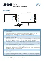
There are relays with four and five contacts, but all relays have winding contacts (control contacts), these are 

85 and 86 contacts (Figure 38). One of these contacts is connected to the “+” of the power supply, and the second 

to any negative control output of the device (contacts 8, 9, 10 and 11 of the Microfit-14 connector). All connections 
must be made through the fuse. 


Figure 38. Designation of the external relay contacts 

 
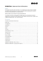
When voltage is applied to control contacts, relay is activated and closes or opens the electrical circuit with 

power contacts. Power contacts are always marked as 30, 87 and 87a. The 30th pin is always in the relay. Without 
applying voltage to the winding contacts, it is permanently closed to contact 87a. If a signal is applied to the winding, 

then the 30th contact is disconnected from 87a and connected to 87. 87a or 87 contacts may be absent, then the 
relay will only work to turn on or off (closing-opening) the power circuit. 


30

85

86

87a

87


Figure 39. Five-contact relay diagram 

 
Such relay can be used for example, when connecting an automotive electromechanical lock (Figure 40). 


Attention! 

When controlling the inductive load, which is the winding of the relay, reverse currents with a potential of 

more than 200 V can occur. Such a voltage can destroy the control transistor of the device output. To limit backflow 
emissions, it is necessary to connect an additional 1N4007 diode (1A, 1000V) in parallel to the relay coil, as indicated 

in figure 40 


At the stage of correctness verification of the connection and settings of the device, it is not recommended to 

include actuators in the relay circuit directly. It is advisable to do this at the final stage of testing. 


Содержание SIGNAL S-2654

Страница 1: ...GPS GLONASS TRACKING EQUIPMENT SIGNAL S 2654 Operations manual Installation and connection of the device v1 0 MOSCOW 2020...

Страница 2: ...terested in constantly improvement of the manufactured products quality Please contact our technical support by email address support navtelecom ru should you have any questions or problems with the d...

Страница 3: ...18 2 3 GSM and GLONASS GPS antennas connection 20 2 4 Power connection 20 2 5 Universal inputs connection 21 2 5 1 Analog sensors connection 21 2 5 2 Discrete sensors connection 21 2 5 3 Pulse frequen...

Страница 4: ...c mode control of cargo safety by comprehensive measures improving driver and passenger s safety 1 3 Operational principles The device during its operation continuously monitors the status of the conn...

Страница 5: ...olonged overvoltage up to 200V yes Current consumption at 12 V voltage in operation mode on average3 mA 80 Current consumption at 12 V voltage with turned off GLONASS and GSM modules is no more than m...

Страница 6: ...D card no less than 2 000 000 per 1 Gb Accelerometer Accelerometer with built in configured shock sensors displacement and tilt sensors yes Measured acceleration range g 24 Acceleration errors in the...

Страница 7: ...a encryption according to the AES128 standard in data transfer yes Real mileage measurement algorithm with the terrain features yes Sensors selection for coordinate averaging yes Configuration of data...

Страница 8: ...ort sending pictures to the server upon the request yes Using of information from tire pressure sensors Pressure Pro TPMS 6 13 from Parkmaster B Tag from Bridgestone TM508T22U and TD 18 20 21 yes Oper...

Страница 9: ...annot be used in high humidity high and low ambient temperatures Operation is permitted under the conditions specified by the manufacturer Not to hit not to deform not to disassemble not to close cont...

Страница 10: ...on of 2 way speakerphone interface SMA connector for connecting a GSM antenna on the left SMA connector for GLONASS GPS antenna connection on the right On the side of the device unit figure 2 is locat...

Страница 11: ...1 2 5 Fuse holder 1 6 14 pin connector of Microfit 14 with two power wires 1 7 6 contact connector of Microfit 6 type 1 8 4 contact connector of Microfit 4 type 1 9 Cable set of 10 installation wires...

Страница 12: ...Figure 9 4 pin connector of Microfit 4 type Figure 10 Interface cable with MiniUSB connector Some cases may require connection of additional equipment not included in the standard equipment set for e...

Страница 13: ...Figure 11 Fuel level sensor Figure 12 Tachograph Figure 13 External LED Figure 14 Temperature sensor...

Страница 14: ...angent G 2500 Figure 16 TouchMemory contact key reader The manufacturer reserves the right to complete the devices with equipment whose set appearance and characteristics differ from those shown in th...

Страница 15: ...em LED indicator 4 GLONASS GPS LED indicator 5 GSM antenna connector 6 GLONASS GPS antenna connector 7 fixing hole 8 4 pin connector 9 14 pin connector 10 6 pin connector 11 MiniUSB connector 12 SIM c...

Страница 16: ...Figure 19 Figure 20...

Страница 17: ...1 Hz to 2000 Hz and analog voltage from 0 V to 31 V FLS impulse fuel consumption sensors DRL buttons or switches Attention It is prohibited to apply a voltage more than 50 V to the device universal i...

Страница 18: ...bus adapter tachographs RFID MODBUS devices etc The digital interface RS 485 is designed for connection of various devices transmitting and receiving information on this interface for example fuel le...

Страница 19: ...of the connection and settings of the device it is not recommended to directly include actuating devices in the output circuits It is advisable to do this at the final stage of verification The power...

Страница 20: ...ion If the SIM card is locked with a PIN code it is necessary to unlock it by inserting the SIM card into a mobile phone or specify the PIN code of this card in the device settings in the Data transmi...

Страница 21: ...ion 2 4 Power connection The power supply of the system is carried out from the on board network of the car which should within the limits indicated in Table 1 in the section Basic technical character...

Страница 22: ...ltage has to be monitored the voltage measurement profile must be set in the inputs setting In this case the function of adjustable averaging of measured values and the setting of the threshold level...

Страница 23: ...resistor when operating with sensors which operates on by ground Rpu CPU_adc R1 R2 UIN C1 CPU_pull up VDD Figure 28 Connection of normally open NO sensors Rpu CPU_adc R1 R2 UIN C1 CPU_pull up VDD Figu...

Страница 24: ...cle ignition line and make the appropriate setting in the configuration However such connection is not mandatory In addition to the source of notifications about turning on and turning off events the...

Страница 25: ...ry to set the threshold level of fixation correctly in order the device correctly determine the frequency or calculate the pulses Connecting pulse or frequency sensors the output of which is implement...

Страница 26: ...n it connects the external load to the power supply to the ground The character of the controlling signal depending on the chosen mode can be permanent signal or periodic Settings of the outputs are m...

Страница 27: ...motive LED lamps It is only necessary to select the LED lamp under the desired voltage of the on board vehicle network 4 2 3 1 14 7 13 6 12 5 11 4 10 3 9 8 2 1 6 5 4 3 2 1 Fuse 1 GND Car battery 1 2 k...

Страница 28: ...wer contacts are always marked as 30 87 and 87a The 30th pin is always in the relay Without applying voltage to the winding contacts it is permanently closed to contact 87a If a signal is applied to t...

Страница 29: ...into it at the manufacturing plant by which the device identifies this sensor Saving the key codes in the device s memory allows to use identification when changing the security mode activating the ou...

Страница 30: ...t all sensors must be connected to one common two wire cable called as bus or trunk It is important not to leave open the end of the bus that is opposite to the connected device it should be closed by...

Страница 31: ...connector The nominal input voltage of the audio signal at the device LOUT output is 500 mV If the amplifier has 2 channels then to increase the power you can connect both amplifier channels in paral...

Страница 32: ...Such a reader allows to receive data from the CAN bus of the car without physically connecting and breaking the insulation of the wires thus avoiding problems with warranty service for new cars The d...

Страница 33: ...Note There can be several CAN buses in the vehicle while information required to the user can be transmitted in different buses Since the terminal has only one CAN interface it is impossible to recei...

Страница 34: ...in the range from 5 to 12 V relative to the sensor supply On the Rx line the voltage will be close to 0 2 12 RS 485 interface connection The digital interface RS 485 is designed to connect devices tra...

Страница 35: ...on when the speakerphone is established with the device An electret microphone capsule is connected to pins 1 MIC and 3 MIC This microphone capsule is used in computer microphones in a compact enclos...

Страница 36: ...1 second off There is a registration in the cellular network of the operator Weak signal 2 short flashes 1 second off There is a registration in the cellular network of the operator Medium quality si...

Отзывы: