

© 2012
Nautilus Hyosung Inc.
All Rights Reserved.
1-3
Installation Manual
Chapter1.Preface
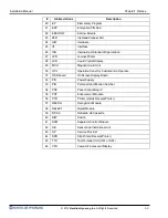
#
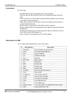
Abbreviations
Description
20
EP
Elementary Program
21
EPP
Encryption PIN Pad
22
ESCROW
Escrow Module
23
FELT
Ink Head Cleaner Felt
24
H/W
Hardware
25
I/F
Interface
26
ISO
International Standard Organization
27
JPR
Journal Printer
28
LCD
Liquid Crystal Display
29
MCU
Magnetic Card Unit
30
OPL
Operation Panel for Customers to Operate
31
OSD board
On Screen Display Board
32
P/S
Power Supply
33
PIN
Personal Identification Number
34
PNC
Panel Control Board
35
PRT
Endorsement Module
36
PTR
Printer (mainly Receipt Printer)
37
RECOG
Recognition Module
38
REJECT
Reject Module
39
RT/A6
Retract & A6 Cassette
40
S/W
Switch
41
SCM
Separator Control Module
42
SIU
Sensor and Indications Unit
43
SP
Service Provider
44
SPR
Slip Printer (Receipt Printer)
45
TTU
Text Terminal Unit (OPL or SPL)
46
VFD
Vacuum Fluorescent Display
Содержание MX7600I
Страница 1: ...Installation Manual MX7600I System V01 00 04 2015 04 12 2012 Nautilus Hyosung Inc All Rights Reserved...
Страница 22: ...2012 Nautilus Hyosung Inc All Rights Reserved 3 9 Installation Manual Chapter3 Installation Information...
Страница 38: ...2012 Nautilus Hyosung Inc All Rights Reserved Notes 1 Installation Manual Notes Notes...