


Vector-LP Radio Beacon Transmitter Technical Instruction Manual
Page
2-9
Section 2 Preparation for Use and Installation
Issue 1.1
2.2.11 External Interlocks
The external electrical interlock circuit
connects between
INTERLOCK
terminals
TB1-19 and TB1-20 of the remote interface
PWB. When it is safe to produce an RF
output, the circuit must be closed and the
transmitter must be ap24 V to
TB1-20. When it is not safe to produce RF
output (one or more of the external interlock
switches activated), the circuit must provide
an open circuit to TB1-20. You can install
any number of serial interlock switches,
pr24 V is removed from TB1-20 if
any interlock switch is activated.
NOTE
Transients may be induced on the 24 V
source if the external wiring is lengthy. To
prevent this, install a relay controlled by
external interlock switches near the remote
interface PWB. Connect it as a fail-safe relay
(energized when the interlock circuit is
closed, de-energized when it is opened) with
its normally open contacts interconnecting
TB1-19 and TB1- 20.
2.2.12 Remote Control Circuits
You can control and monitor transmitter
functions by connecting to the remote
interface PWB using a conventional remote
interface or using an RS232 or RS422 serial
port (see 2.2.15 for a description of the serial
port features). You can control the on/off
status, standby code 1, and standby code 2
using switching circuits that are either a
single ended input or a differential input. The
charger alarm can also be monitored
remotely.
NOTE
External control circuits connect to the
transmitter circuits through opto- couplers on
the remote interface PWB. The opto-
couplers buffer/isolate the external circuits
and prevent any transients from affecting
transmitter operation. These opto-couplers
only have influence when
Remote
control is
selected at the transmitter. The remote
interface PWB contains selection circuits
that allow the user to select an internal
(single ended input) or external (differential
input) dc power supply as the current source
for the opto-coupler associated with each
controlled function
.
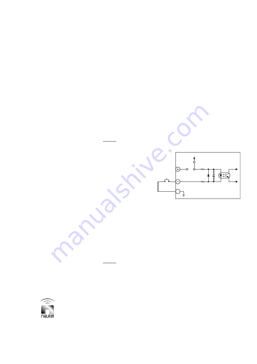
The switching circuit for each remotely
controlled function must be the equivalent of
a normally open/held closed spring-loaded
(momentary) switch. Each must be
configured to operate as a single ended
input using the transmitter's unregulated
+24 V as the dc volts source (see Figure
2-3) or as a differential input using an
external dc power supply (24 V to 30 V) as
the dc volts source (see Figure 2-4). Each
control function has positive and negative
input terminals on the remote interface PWB
to accommodate the selected configuration.
Figure 2-3 Single Ended Input Selected
Single Ended Input (Internal V dc)
When using the transmitter’s +24 V as the
current source for a control function’s opto-
coupler, configure the remote interface PWB
circuit for a single ended input. Configure the
2-socket shunt post on the 3-pin header
associated with the control function as
shown in Figure 2-3. Apply a negative logic
command (current-sink-to-ground is active)
to the control’s negative (-) input terminal.
The ground must come from TB1-24.
1
2
3
INTERFACE
PWB
REMOTE SELECTION CIRCUITRY
CONFIGURED FOR INTERNAL
DC VOLTS
REMOTE
+24V
E#
1
S1970005 V1


