©
National Instruments Corporation
11
SCXI Quick Start Guide
Multichassis System
1.
Connect one end of a 68-pin shielded cable to the DAQ communicating device.
2.
Connect the other end of the cable to the SCXI-1346 in chassis ID
n
labeled
FROM DAQ
BOARD OR PREVIOUS CHASSIS
.
3.
Connect a 68-pin shielded cable to the SCXI-1346 in chassis
n
labeled
TO NEXT CHASSIS
.
4.
Connect the other end of the cable to the SCXI-1346 in chassis ID
n
+1 labeled
FROM DAQ
BOARD OR PREVIOUS CHASSIS
.
5.
Repeat steps 3 and 4 for the remaining chassis until you reach the last chassis.
6.
Connect the 68-pin shielded cable to the next to the last chassis in the slot labeled
TO NEXT
CHASSIS
.
7.
Connect the other end of the cable to the SCXI-1349 in the last chassis.
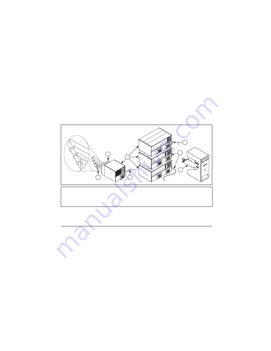
Figure 12.
Completed SCXI System
Step 9. Power On the SCXI Chassis
If you are using an SCXI chassis, the chassis power switch is shown in Figure 3. If you are using
a PXI/SCXI combination chassis, the PXI and chassis power switches are shown in Figure 4.
When the controller recognizes a USB device such as an SCXI-1600 module, the LED on the
module front panel blinks or lights up. Refer to the device documentation for LED pattern
descriptions and troubleshooting information.
Windows Device Recognition
Windows versions earlier than Windows Vista recognize any newly installed device when the
computer restarts. Vista installs device software automatically. If the Found New Hardware
wizard opens,
Install the software automatically
as recommended for each device.
1
Shielded Cable Connected to
SCXI-1349 Cable Adapter
2
Shielded Cable Connected to
SCXI-1346 Cable Adapter
3
DAQ Device
4
Shielded Cable to
DAQ Device
5
Terminal Blocks
6
Sensors
7
SCXI Chassis
HV
–
+
V
–
+
mV
–
+
3
1
2
4
5
6
7
HV
–
+
V
–
+
mV
–
+
Содержание SCXI-116 Series
Страница 1: ...SCXI 1143...


