background image

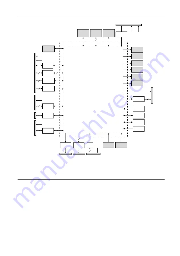
Figure 2.

 NI roboRIO Hardware Block Diagram

CAN

Port

Xilinx Zynq-7020

Processor/FPGA

(LabVIEW RT)

USB 

Device

Port

USB 

Host

Ports

10/100 

Ethernet

Port

Status LED

Comm LED

Radio LED

Mode LED

RSL LED

Power LED

+3.3 V

+5.0 V

16

16

2

4

UART

DIO

Analog Out

Analog In

myRIO

Expansion

Port (MXP)

User

Button

Reset

Button

PWM

Port

10

10

+6.0 V

PWM

SPI

SPI Port

+5.0 V

+3.3 V

7

7

2

RS-232

RS-232

Port

2

I

2

C

I

2

C

Port

2

+3.3 V

DIO

Port

DIO

10

10

+5.0 V

Watchdog

Nonvolatile

Memory

DDR3

Acceler-

ometer

RSL

RSL

Port

Relay

8

8

RELAY

Port

4

+5.0 V

AI

ANALOG IN

Port

Setting Up the NI roboRIO

Connecting to Power

The NI roboRIO requires an external power supply that meets the specifications in the 

Power

Requirements

 section of the 

NI roboRIO Specifications

. The NI roboRIO filters and regulates

the supplied power and provides power for all of the I/O and user voltage. The NI roboRIO
has one layer of reverse-voltage protection.

Complete the following steps to connect a power supply to the chassis.
1.

Ensure that the power supply is turned off.

4

  | 

ni.com

  | 

NI roboRIO User Manual

Содержание roboRIO

Страница 1: ...C SCL SCL 3 3V SDA 3 3V SDA RS 232 RS 232 TXD TXD RXD RXD RSL RSL MISO MISO 3 3V 3 3V COMM COMM MODE MODE RSL RSL RELAY RELAY 0 0 1 1 FWD FWD 5V 5V S S S S REV REV 2 2 3 3 0 0 1 1 1 1 33 33 2 2 3 3 3...

Страница 2: ...L Port 11 Relay Port 11 AI Port 12 PWM Port 12 SPI Port 13 Signal Ground References 13 Interfaces 14 AI Channels 14 AO Channels 14 DIO PWM and Relay Lines 15 UART and RS 232 Lines 16 SPI Lines 16 I2C...

Страница 3: ...with the regulatory requirements and limits for electromagnetic compatibility EMC stated in the product specifications These requirements and limits provide reasonable protection against harmful inter...

Страница 4: ...5 0 V Watchdog Nonvolatile Memory DDR3 Acceler ometer RSL RSL Port Relay 8 8 RELAY Port 4 5 0 V AI ANALOG IN Port Setting Up the NI roboRIO Connecting to Power The NI roboRIO requires an external pow...

Страница 5: ...power supply Powering On the Device The NI roboRIO runs a power on self test POST when you apply power to the device During the POST the Power and Status LEDs turn on When the Status LED turns off the...

Страница 6: ...Voltage Rail Description 6 V Power from PWM ports for use with servos 5 V Power for DIO and AI ports for sensors and power for the MXP for powering expansion circuits 3 3 V Power for I2C SPI and the M...

Страница 7: ...ing systems continue to function normally with valid data and communication FPGA processor RAM disk and user code USB power and communication Radio if powered by USB Ethernet CAN AI and AO I2C SPI RS...

Страница 8: ...16 15 14 13 12 11 10 9 8 7 6 5 4 3 2 1 1 33 Table 3 MXP Signal Descriptions Signal Name Reference Direction Description 5V DGND Output 5 V power output AI 0 3 AGND Input 0 V to 5 V referenced single e...

Страница 9: ...following figure and table describe the CAN port pins and signals Figure 5 CAN Port Pinout H YEL L GRN Table 4 CAN Port Signal Descriptions Signal Name Direction Description L GRN Input Output CAN bus...

Страница 10: ...signals Figure 7 RS 232 Serial Port Pinout RXD TXD Table 6 RS 232 Serial Port Signal Descriptions Signal Name Direction Description TXD Output Serial transmit output with 5 V to 15 V signal levels Re...

Страница 11: ...ort The following figure and table describe the RSL port pins and signals Figure 9 RSL Port Pinout S Table 8 RSL Port Signal Descriptions Signal Name Direction Description S Output Switched power outp...

Страница 12: ...pins and signals Figure 11 AI Port Pinout S 5V 1 2 0 3 Table 10 AI Port Signal Descriptions Signal Name Direction Description S AI 0 3 Input 0 V to 5 V referenced single ended AI channels Refer to the...

Страница 13: ...al Descriptions Signal Name Direction Description 3 3V Output 3 3 V power output 5V Output 5 V power output CS 0 3 Output SPI with 3 3 V output 3 3 V 5 V compatible input Refer to the SPI Lines sectio...

Страница 14: ...s the AI topology of the NI roboRIO Figure 14 NI roboRIO AI Circuitry MUX ADC AI0 AI1 AI2 AI3 AI0 AI1 AI2 AI3 0 5 V Expansion port MXP Integrated AI port AO Channels The NI roboRIO MXP has two AO chan...

Страница 15: ...resistors to 3 3 V as shown in the following figure Figure 17 DIO Lines with 2 2 k Pullup Resistors to 3 3 V 2 2 k FPGA Bus Switch DIO SCL SDA 3 3 V SCLK MOSI MISO on the SPI port and the lines on the...

Страница 16: ...four devices by using each of the four Chip Select CS lines I2C Lines The I2C lines can be used to connect to a network of I2C slave devices USB Device Port You can deploy and debug code by connecting...

Страница 17: ...ht 16 212 3 906 Maximum Positive Reading 2047 3 906 7 996 Maximum Negative Reading 2048 3 906 8 000 Front Panel Buttons Reset Button Pressing and releasing the Reset button restarts the processor and...

Страница 18: ...tion Red Solid Brownout condition detected The user rail and outputs are disabled Status LED The Status LED is a single color yellow LED The Status LED is off during normal operation The NI roboRIO ru...

Страница 19: ...ic conditions for a USB connected radio as shown in the following table Table 15 Radio LED Indications Color State Indication Off Off Green and Red disabled Green Solid Green enabled Red Solid Red ena...

Страница 20: ...enabled Red Solid Red enabled Yellow Solid Green and Red enabled RSL Safety LED The RSL LED is a single color yellow LED that functions identically to the RSL which is an external indicator connected...

Страница 21: ...7 in 52 76 mm 2 077 in 45 14 mm 1 777 in 22 26 mm 0 876 in 8 44 mm 0 332 in 0 0 mm 0 in 0 0 mm 0 in 7 16 mm 0 282 in 8 42 mm 0 332 in 19 52 mm 0 769 in 135 47 mm 5 333 in 132 61 mm 5 221 in 130 72 mm...

Страница 22: ...M COMM MODE MODE RSL RSL RELAY 0 1 FWD S S REV 2 3 0 1 1 33 2 3 3 2 1 0 7 9 8 6 5 4 4 5 6 7 8 9 0 1 2 3 ANALOG IN RESET ACCELEROMETER PWM DIO Y Z X USER S S 5V 5V 6V INPUT 7 16V 45W MAX 146 15 mm 5 75...

Страница 23: ...319 in 0 0 mm 0 in 3 84 mm 0 151 in 142 31 mm 5 603 in 4 40 Screw Insert Figure 22 NI roboRIO Dimensions Side 5 71 mm 0 225 in 129 59 mm 5 102 in 122 39 mm 4 819 in 20 79 mm 0 819 in 13 59 mm 0 535 in...

Страница 24: ...ch as AndyMark part number am 0836 Using cable ties to secure one corner of the NI roboRIO to perfboard Using screws to secure the bottom of the NI roboRIO to a metal plate Method One Using Cable Ties...

Страница 25: ...Figure 24 Step 2 to Secure One Edge of the Device Figure 25 Step 3 to Secure One Edge of the Device NI roboRIO User Manual National Instruments 25...

Страница 26: ...Method Two Using Cable Ties to Secure One Corner of the NI roboRIO to Perfboard The following figures show how to secure one corner of the NI roboRIO to perfboard Figure 27 Step 1 to Secure One Corne...

Страница 27: ...Figure 28 Step 2 to Secure One Corner of the Device Figure 29 Step 3 to Secure One Corner of the Device NI roboRIO User Manual National Instruments 27...

Страница 28: ...Figure 30 Step 4 to Secure One Corner of the Device Figure 31 Step 5 to Secure One Corner of the Device 28 ni com NI roboRIO User Manual...

Страница 29: ...length is 7 94 mm 0 313 in Figure 32 Mounting NI roboRIO Using Screws 2 1 1 Metal Mounting Plate 2 4 40 Screws x 4 Compatible USB and Ethernet Cables The following table lists the USB and Ethernet ca...

Страница 30: ...s Visit ni com services for NI Factory Installation Services repairs extended warranty and other services Visit ni com register to register your National Instruments product Product registration facil...

Страница 31: ...and third party legal notices in the readme file for your NI product Refer to the Export Compliance Information at ni com legal export compliance for the National Instruments global trade compliance p...

Отзывы: