


© National Instruments
|
2-17
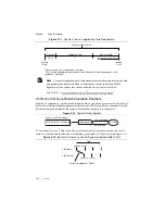
Triggering and Filter Delay
The NI PXIe-4302/4303 interprets triggers based on where they occur in time. The hardware
automatically compensates for its group delay such that data from this module will line up
closely in time with the occurrence of the trigger event. However, the group delay affects how
long it takes to receive data when starting an acquisition. Since linear phase FIR filters are used
in the digital filtering, it is necessary to wait for the filter group delay to elapse after sending a
sync pulse before the start trigger can be correctly handled in time. Step 6 in the
section allows NI-DAQmx to handle this delay automatically. After the digital
start trigger, you cannot read data for the first sample in software until the digital filter group
delay has elapsed. Therefore, it takes a total of twice the digital filter group delay to start an
acquisition. You can insert additional time between when the sync pulse occurs and when the
start trigger occurs. This will not affect the time it takes before samples are available after the
start trigger, which is always the group delay time. Group delay time increases as sample rates
decrease. Refer to the
NI PXIe-4302/4303 Specifications
document for details regarding the
group delay at different sample rates.
Synchronization
Some applications require tight synchronization between input and output operations on
multiple modules. Synchronization is important to minimize skew between channels and to
eliminate clock drift between modules in long-duration operations. You can synchronize the
analog input operations on two or more NI PXIe-4302/4303 modules to extend the channel count
for your measurements. In addition, the NI PXIe-4302/4303 can synchronize with certain DSA
modules, such as the NI PXIe-449x modules, using Reference Clock Synchronization.
Reference Clock Synchronization
With reference clock synchronization, master and slave modules generate their ADC
oversample clock from the shared 100 MHz reference clock from the PXIe backplane
(PXIe_CLK100). The backplane supplies an identical copy of this clock to each peripheral slot.
In addition, multiple chassis can be synchronized by using a timing and synchronization board
to lock the 100 MHz clock across chassis.
When you acquire data from multiple modules within the same NI-DAQmx task, NI-DAQmx
will automatically handle all of the Reference Clock Synchronization details required to
synchronize the modules within the task. This is known as a Multi-Device Task.
To perform Reference Clock Synchronization when using multiple NI-DAQmx tasks that are
acquiring at the same rate, complete the following steps to synchronize the hardware.
1.
Specify PXIe_CLK100 as the reference clock source for all modules to force all the
modules to lock to the reference clock on the PXIe chassis.
2.
Choose an arbitrary NI PXIe-4302/4303 master module to issue a sync pulse on one of the
PXIe Trigger lines. The sync pulse resets the ADCs and oversample clocks, phase aligning
all the clocks in the system to within nanoseconds.
3.
Configure the rest of the modules in your system to receive their sync pulse from the sync
pulse master module. This will ensure all ADCs are running in lockstep.


