


2-10
|
ni.com
Chapter 2
Using the Module
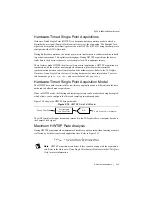
Hardware-Timed Single Point Mode. In Hardware-Timed Single Point Mode the oversampled
data is filtered with a much looser filter to reduce the group delay.
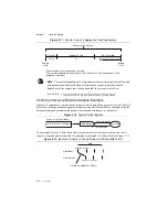
Buffered Mode Acquisitions
In buffered mode, the NI PXIe-4302/4303 uses a combination of analog and digital filtering to
provide an accurate representation of in-band signals while rejecting out-of-band signals. These
filters discriminate between signals based on the frequency range, or bandwidth, of the signal.
The three important bands to consider are the passband, the stopband, and the alias-free
bandwidth.
In buffered mode, the NI PXIe-4302/4303 accurately represents signals within the passband, as
quantified primarily by passband flatness and phase nonlinearity. All signals that appear in the
alias-free bandwidth are either unaliased signals or signals that have been filtered by at least the
amount of the stopband rejection.
Anti-Alias Filters
A digitizer or ADC might sample signals containing frequency components above the Nyquist
limit. The undesirable effect of the digitizer modulating out-of-band components into the
Nyquist bandwidth is aliasing. The greatest danger of aliasing is that you cannot determine if
aliasing occurred by looking at the ADC output. If an input signal contains several frequency
components or harmonics, some of these components might be represented correctly while
others contain aliased artifacts.
Lowpass filtering to eliminate components above the Nyquist frequency either before or during
the digitization process can guarantee that the digitized data set is free of aliased components. In
buffered mode, the NI PXIe-4302/4303 modules employ both digital and analog lowpass filters
to achieve this protection.
In buffered mode, the NI PXIe-4302/4303 modules use an oversampled architecture and sharp
digital filters
1
with cut-off frequencies that track the sampling rate. Therefore the filter
automatically adjusts to follow the Nyquist frequency. Although the digital filter eliminates
almost all out-of-band components, it is still susceptible to aliases from certain narrow frequency
bands located at frequencies far above the sampling rate. These frequencies are referred to as the
ADC alias holes.
To minimize the error from the ADC alias holes, the NI PXIe-4302/4303 modules feature a
fixed-frequency analog filter. This analog filter removes high-frequency components in the
analog signal path before they reach the ADC. This filtering addresses the possibility of
high-frequency aliasing from the narrow bands that are not covered by the digital filter.
1
Looser filters with degraded alias-free bandwidth are used for sample rates < 25 Hz. This is done in order
to reduce the large group delays associated with filtering at lower sample rates. Refer to the
NI PXIe-4302/4303 Specifications
document for performance at lower rates.


