


2-6
|
ni.com
Chapter 2
Using the Module
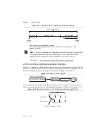
Figure 2-7.
Connecting a Loop-Powered Current Transducer
Figure 2-8.
Connecting a Three-Wire Current Transducer
Module Pinout
Table 2-1 shows the pinout of the front connector of the NI PXIe-4302/4303. Refer to the
section for definitions of each signal. Refer to the
NI PXIe-4302/4303 and TB-4302/4302C User Guide and Terminal Block Specifications
for
signal locations on the terminal blocks.
AI
Extern
a
l
Power
Su
pply
2 A
M
a
x
AI
S
EN
S
E
AIGND
PXIe-4
3
02/4
3
0
3
TB-4
3
02C
AI+
AI–
AIGND
Extern
a
l
Bi
as
Re
s
i
s
tor
Loop-
Powered
C
u
rrent
Tr
a
n
s
d
u
cer
+
–
Protection
Circ
u
it
S
h
u
nt
5
Ω
V
su
p
V
su
p
AI
Extern
a
l
Power
Su
pply
2 A
M
a
x
AI
S
EN
S
E
AIGND
PXIe-4
3
02/4
3
0
3
TB-4
3
02C
AI+
AI–
AIGND
Extern
a
l
Bi
as
Re
s
i
s
tor
Three
Wire
C
u
rrent
Tr
a
n
s
d
u
cer
+
–
Protection
Circ
u
it
S
h
u
nt
5
Ω
+
O
u
t
–
V
su
p
V
su
p


