NI 9144 User Guide and Specifications
|
© National Instruments
|
55
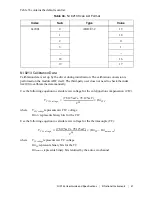
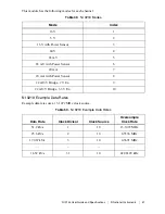
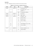
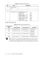
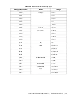
The operating modes and ranges, in the order they are defined in the calibration table for each
channel, are listed in Table 54.
Table 54.
NI 9219 Channel Calibration
Entry Number
Mode
Range
1
Voltage
±60 V
2
±15 V
3
±4 V
4
±1 V
5
±125 mV
6
Current
±25 mA
7
4-Wire Resistance
10 k
Ω
8
1 k
Ω
9
2-Wire Resistance
10 k
Ω
10
1 k
Ω
11
Thermocouple
—
12
4-Wire RTD
Pt1000
13
Pt100
14
3-Wire RTD
Pt1000
15
Pt100
16
Quarter-Bridge
350
Ω
17
120
Ω
18
Half-Bridge
±500 mV/V
19
Reserved
—
20
Full-Bridge
±62.5 mV/V
21
±7.8 mV/V

