70
|
ni.com
|
NI 9144 User Guide and Specifications
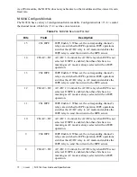
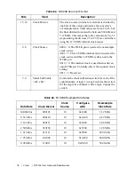
Table 70.
NI 9233 Scan List Format
Bits
Field
Description
7
Turbo Disable
(NI 9233 only)
0 = The conversion rate is equal to the oversample
clock rate/128.
Set to 0 for conversion rates > 25 kS/s.
1 = The conversion rate is equal to the oversample
clock rate/256.
Set to 1 for conversion rates < 25 kS/s.
6..2
Clock Divisor
The clock source (internal or external) is divided by this
value and used as the converters’ oversample clock. Valid
values are from 2 to 31, but the final divided clock must be
between 512 kHz and 6.4 MHz. This means that only values
from 2 to 25 are valid when using the 12.8 MHz internal
clock source.
1..0
Clock Source = 2
0b00 = 0: The OCLK pin is used as the oversample clock
source.
0b01 = 1: The 12.8 MHz internal clock is used as the clock
source and this 12.8 MHz is driven onto the OCLK pin.
0b10 = 2: The internal clock is used but not driven onto
OCLK pin. Currently, this is the required clock setting.
0b11 = 3: Reserved.
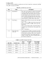
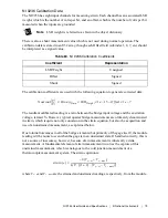
Table 71.
NI 9233 Example Data Rates
Data Rate
Turbo
Disable
Clock
Divisor
Clock
Source
Configure
ADC
Oversample
Clock Rate
50.000 kS/s
0
00010
10
0x0A
6.40 MHz
25.000 kS/s
1
00010
10
0x8A
6.40 MHz
12.500 kS/s
1
00100
10
0x92
3.20 MHz
10.000 kS/s
1
00101
10
0x96
2.56 MHz
6.250 kS/s
1
01000
10
0xA2
1.60 MHz
5.000 kS/s
1
01010
10
0xAA
1.28 MHz
3.333 kS/s
1
01111
10
0xBE
853 kHz
3.125 kS/s
1
10000
10
0xC2
800 kHz
2.500 kS/s
1
10100
10
0xD2
640 kHz
2.000 kS/s
1
11001
10
0xE6
512 kHz


