background image

7

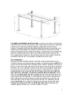
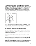
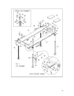
Find the leg caps 

(4 each), 1/2” x 7” bolts (4 each), 1/2” x 1 1/4” bolts (4 

each), 1/2” nuts (8 each) and 1/2 “ flat washers (16 each), 

holes for cable face 

towards the center of the lift. Secure the leg caps with 

1/2” x 1 1/4” bolts

. Place 

the bolts with washers in through channel and secure with washers and nuts on 
the outside of the leg. Install the 

1/2” x 7

” bolts through the leg and top cap. 

Install from outside of the leg, and secure with a nut on the inside of the leg. 
Tighten the 

1 1/4” bolt

. Tighten the 7” bolt to a torque of 45 ft-lbs. Do not over 

tighten the 

7” bolt

, as this may warp the column channel and bind the guide 

blocks.

1)

 The cables are already strung and ready to attach to the top of legs.  Before 

doing this you must extend the chrome rod out of the cylinder far enough for the 
cables to reach. If you have the lift on the lowest lock you will need to extend the 
cable approximately 60 inches.

DO NOT USE THE POWER UNIT TO EXTEND THE CYLINDER

Make sure both parts on the cylinder are open to allow the easy flow of air.  
Manually or with a device such as a come along, pull the cylinder out 60 inches.  
Although the cylinder may be difficult to move at first, it is usually much easier 
once you get the first movement.

If you have a compressor you can use air to extend the cylinder.  Place the air 
Into the back port, (the port away from the chrome rod) and blow air into the 
cylinder.

After you have extended the chrome rod attach the cable to the top caps in the 
legs.  Make sure each cable is on the pulleys.  Place both nuts on top of the top 
cap and tighten them together.

Safety Latch Linkage Installation: 

Locate and identify the components needed 

to install the safety latch linkage rods. Install the spacers from on the straight 

Содержание NSS8XLT

Страница 1: ...NSS8XLT NSS8XLT Installation Installation Manual Manual...

Страница 2: ...e done manually 2 If you do not know how to wire your motor get professional help 3 Make sure all cables are on pulleys before operating your lift 4 Always lower your lift onto the safety locks this w...

Страница 3: ...are designed to close when released Do not block open or override them NEVER overload your lift Manufacturer s rated capacity is shown on nameplate affixed to the lift ALWAYS know the gross weight of...

Страница 4: ...for alignment of moving parts breakage of parts or any condition that may affect its operation Do not use lift if any component is broken or damaged NEVER remove safety related components from the lif...

Страница 5: ...er than described This lift is only as strong as the foundation on which it is installed DO NOT install this lift outdoors unless special consideration has been made to protect the power unit from wea...

Страница 6: ...eg with power unit bracket attached NOTE The power unit can be located in two locations shown With an assistant pick up and place one end of the main side track on the crossrail and then pick up and p...

Страница 7: ...r enough for the cables to reach If you have the lift on the lowest lock you will need to extend the cable approximately 60 inches DO NOT USE THE POWER UNIT TO EXTEND THE CYLINDER Make sure both parts...

Страница 8: ...cause a drop in pressure All valve pump and hose connections should be sealed and or capped until just before use All parts should be supplied from manufacture Air hoses can be used to clean fittings...

Страница 9: ...OT RISE Check hose connections Fluid should be pumping through the hose Check fluid level NOTE There will be some initial stretching of the cables in the beginning It will be necessary to readjust the...

Страница 10: ...kage unusual noise or excessive wear must be fixed before using lift PRE OPERATION CHECK The user should perform daily check ATTENTION LOOK OUT Daily check of safety latch system is very important the...

Страница 11: ...11...

Страница 12: ...12...

Страница 13: ...13...

Отзывы: