NARGESA C2006 Скачать руководство пользователя страница 34

C2006 HYDRAULIC SHEAR INSTRUCTIONS BOOK                                                                                                                                        33 


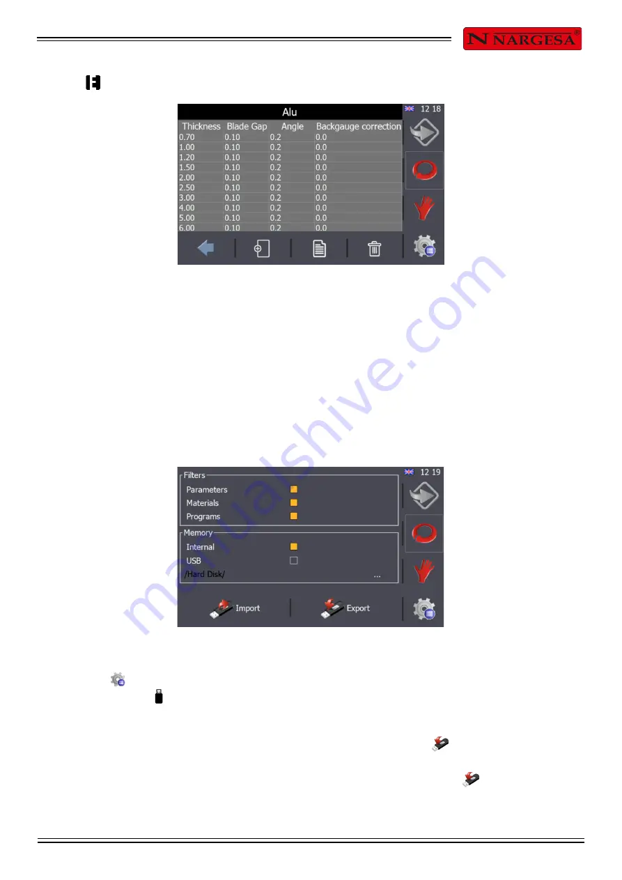
Use        to access the table to manage the material selected. 


The material management option allows various thicknesses, angles, blade separations and gauge 
corrections to be added, changed and removed for each of the table entries. 


The blade separation and blade angle are set at the factory to precise values and changing these values in 
the table will not affect how the shears are used. 


5.20. Import/export parameters, materials and programs  

All the shear settings, predefined material parameters and programs created can be imported and exported 
to create back-ups. 


Press the        button to access the window displayed in the previous figure. Once the menu screen 
appears, press the       button. 


By default, all the filters are active as well as the internal memory option. Press          to save all the 
parameters, materials and programs in the machine's internal memory, creating a back-up copy. A back-up 
copy can also be saved to an external USB by selecting the USB option and pressing          again. 

Содержание C2006

Страница 1: ...INSTRUCTIONS BOOK PRADA NARGESA S L Ctra de Garrig s a Sant Miquel s n 17476 Palau de Santa Eul lia Girona SPAIN Tel 34 972568085 nargesa nargesa com www nargesa com HYDRAULIC SHEAR C2006...

Страница 2: ...Thank you for choosing our machines www nargesa com...

Страница 3: ...tion of the guides 10 3 1 4 Lubrication of the gauge spindles 11 4 INSTALACINSTALLMENT AND START UP 12 4 1 Location of the machine 12 4 2 Dimensions and working site 12 4 3 Admissible outer conditions...

Страница 4: ...17 Alarm management 30 5 18 Input output monitoring 31 5 19 Material management 32 5 20 Import export parameters materials and programs 33 5 21 Remote service 34 5 22 Touch screen calibration 36 6 WA...

Страница 5: ...xternal dimensions of the machine 1 3 Description of the machine The guillotine C2006 has been designed specifically for cutting metal sheets The manufacturer will not take any responsibility for the...

Страница 6: ...BOOK 5 1 4 Identification of the machine Laser Commands control Polycarbonate Front protection Screws to level the machien Lifting spot Power motor Safety Photocell Side protections Stands for the en...

Страница 7: ...5 CV Three phased tension 230 400 V Cutting Capacity mild steel 6 mm Cutting capacity stailess steel 4 mm N of hammers 10 units Cutting length 2030 mm Neck 190 mm Gauge displacement 700 mm Strokes per...

Страница 8: ...ion avoids from acceding to the rammers side Protections in the back side of the machine covering the belts and pulley of the back top the outet ramp for the material and the upper protection cover of...

Страница 9: ...any other side but the indicated one Picture 4 Transportation of the machine 2 2 Storage conditions The machine will not be stored in a place that hasn t got the following requirements Humidity betwe...

Страница 10: ...be checked every 1000 hours of work The oil level sight glass is located at the side of the tank If oil needs to be added fill until the sight glass is completely full Replace the hydraulic oil contai...

Страница 11: ...points Grease up the bolts periodically according to the level of use If it is a steady and daily use they must be greased avery month Rear view of the machine 3 1 3 Lubrication of the guides In order...

Страница 12: ...e folding group We stop the machine and proceed to lubricate the 2 spindles and the 2 guides We put the machine in gear and place the gauge at its minimum height then move it to its maximum height Rep...

Страница 13: ...l the machine by using the screws at the bottom of the machine at each corner Picture 5 Anchor points of the machine 4 2 Dimensions and working site The dimensions of the machine are to be considered...

Страница 14: ...power supply The C2006 shears are equipped with two three phase 230 400 V motors a 0 37 kW motor for the gauge and a 5 5 kW star connected motor which requires a single 240V or 400V power supply If t...

Страница 15: ...for the user of the Guillotine C2006 since it has got important information about the use of it and the peculiar features of the machine Therefore it is advisable to follow step by step the points de...

Страница 16: ...rest position awaiting any command the user orders 5 4 Activating the machine Press the reset button located in the electrical panel This reset button must be pressed each time the machine is turned...

Страница 17: ...message disappears and the following is displayed The following message will appear once the Homing cycle has finalised Cuts can be done manually from this point on by simply entering the information...

Страница 18: ...d by default The mode can be changed simply by pressing The single operational mode works in the following way The blade is lowered while the operator presses down on the pedal If the pedal is release...

Страница 19: ...lly and the operator simply enters the sheets to be cut into the machine The cut counter will increase by one each time the pedal is pressed or each time the shear blade makes a cut and returns to the...

Страница 20: ...ised Once the blade is in the rest position the gauge will automatically return to the programmed position This function can be enabled or disabled in both the manual single and continuous and automat...

Страница 21: ...for example Press the button to activate it Once the required calculations have been done the resulting value can be confirmed as the new cutting dimension by pressing the key The result is now displ...

Страница 22: ...w the same procedure to add more steps To remove a step first select it by clicking on the corresponding tab Then press the icon which is displayed in the top right corner of the window The informatio...

Страница 23: ...for the current step This is done by pressing the button When the gauge is in position press the cutting pedal as instructed on screen The machine will start to do the first 500 mm cut as specified i...

Страница 24: ...displayed as a list of existing programs use the and arrows to navigate through the list and management icons which are located at the bottom of the screen The corresponding functions are described b...

Страница 25: ...e between the size of the part created and the specified cut dimensions Press the button to adjust the gauge A menu window appears on the screen with the following diagram Now press the button to acce...

Страница 26: ...the measured distance is greater than the specified level then this difference should be added to the gauge Zero Position If the distance is less than the specified level then the difference should be...

Страница 27: ...procedure detailed in the corresponding section to do so after enabling the blade adjustment mode During this operating mode the upper blade is lowered when the pedal is pressed When the pedal is rel...

Страница 28: ...e for the side of the sheet between the minimum of 0 and the maximum lateral measurement specified at the factory By changing this value the upper shear blade will only be lowered to the position requ...

Страница 29: ...can be removed by pressing The pop up window will then disappear but a warning icon will appear in the upper right corner of the screen similar to the one displayed below The machine cannot start ope...

Страница 30: ...so remove the pop up message by pressing but as with the general emergency situation the warning icon is displayed in the notifications bar to the right until the blue reset button is pressed On doing...

Страница 31: ...n located inside the machine electrical panel is reset 5 17 Alarm management A new entry is recorded in the alarm log whenever there is an emergency situation due to an emergency stop photocell interr...

Страница 32: ...hey can be filtered by date and category in order to create a detailed list of each of the incidents 5 18 Input output monitoring The machine has a useful tool which can be used to monitor the status...

Страница 33: ...manage them suitably Press the button and then when the menu window appears On doing so the window below is displayed The shears are supplied from the factory with a standard materials table Material...

Страница 34: ...the shears are used 5 20 Import export parameters materials and programs All the shear settings predefined material parameters and programs created can be imported and exported to create back ups Pre...

Страница 35: ...ess The sequence of information that appears on the screen by doing so is as follows 5 21 Remote service The shears can be connected to the Ethernet using a cable supplied for this purpose The IP addr...

Страница 36: ...e following screen will appear The information displayed in the previous image refers to the shear model and serial number as well as the various IT system versions used in the user interface Press to...

Страница 37: ...he menu window Once within the menu press the button The message displayed below will appear on doing so To accept press and the touch screen calibration process will start At this point the informati...

Страница 38: ...ut the protections provided by the machine Do not use cutting tools that are not provided by NARGESA Do not cancel any protection device provided by the machine NARGESA SL will not accept any responsi...

Страница 39: ...ting of different kinds of metal sheet The blades are treated by various processes which reinforces its liability and resistance at a normal use condition The guillotine C2006 has and upper blade and...

Страница 40: ...List of parts Detail of treaders Detail of guided gauge Detail of dirving gauge Detail of Hydraulic kit Detail of activation triangular connecting rod Detail of triangular rod Detail of cylinder Elec...

Страница 41: ...C2006 HYDRAULIC SHEAR INSTRUCTIONS BOOK A 2 A1 List of parts...

Страница 42: ...C2006 HYDRAULIC SHEAR INSTRUCTIONS BOOK A 3...

Страница 43: ...C2006 HYDRAULIC SHEAR INSTRUCTIONS BOOK A 4...

Страница 44: ...C2006 HYDRAULIC SHEAR INSTRUCTIONS BOOK A 5...

Страница 45: ...C2006 HYDRAULIC SHEAR INSTRUCTIONS BOOK A 6...

Страница 46: ...C2006 HYDRAULIC SHEAR INSTRUCTIONS BOOK A 7...

Страница 47: ...C2006 HYDRAULIC SHEAR INSTRUCTIONS BOOK A 8...

Страница 48: ...C2006 HYDRAULIC SHEAR INSTRUCTIONS BOOK A 9...

Страница 49: ...C2006 HYDRAULIC SHEAR INSTRUCTIONS BOOK A 10 A2 Detail of treaders...

Страница 50: ...C2006 HYDRAULIC SHEAR INSTRUCTIONS BOOK A 11 A3 Detail of guided gauge...

Страница 51: ...C2006 HYDRAULIC SHEAR INSTRUCTIONS BOOK A 12...

Страница 52: ...C2006 HYDRAULIC SHEAR INSTRUCTIONS BOOK A 13 A4 Detail of dirving gauge...

Страница 53: ...C2006 HYDRAULIC SHEAR INSTRUCTIONS BOOK A 14...

Страница 54: ...C2006 HYDRAULIC SHEAR INSTRUCTIONS BOOK A 15 A5 Detail of Hydraulic kit...

Страница 55: ...C2006 HYDRAULIC SHEAR INSTRUCTIONS BOOK A 16...

Страница 56: ...C2006 HYDRAULIC SHEAR INSTRUCTIONS BOOK A 17...

Страница 57: ...C2006 HYDRAULIC SHEAR INSTRUCTIONS BOOK A 18 A6 Detail of activation triangular connecting rod...

Страница 58: ...C2006 HYDRAULIC SHEAR INSTRUCTIONS BOOK A 19 A7 Detail of triangular rod...

Страница 59: ...C2006 HYDRAULIC SHEAR INSTRUCTIONS BOOK A 20 A8 Detail of cylinder...

Страница 60: ...C2006 HYDRAULIC SHEAR INSTRUCTIONS BOOK A 21...

Страница 61: ...C2006 HYDRAULIC SHEAR INSTRUCTIONS BOOK A 22 A9 Electric box...

Страница 62: ...C2006 HYDRAULIC SHEAR INSTRUCTIONS BOOK A 23 A10 Electric maps...

Страница 63: ...C2006 HYDRAULIC SHEAR INSTRUCTIONS BOOK A 24...

Страница 64: ...C2006 HYDRAULIC SHEAR INSTRUCTIONS BOOK A 25...

Страница 65: ...C2006 HYDRAULIC SHEAR INSTRUCTIONS BOOK A 26...

Страница 66: ...C2006 HYDRAULIC SHEAR INSTRUCTIONS BOOK A 27...

Страница 67: ...C2006 HYDRAULIC SHEAR INSTRUCTIONS BOOK A 28...

Страница 68: ...C2006 HYDRAULIC SHEAR INSTRUCTIONS BOOK A 29...

Страница 69: ...C2006 HYDRAULIC SHEAR INSTRUCTIONS BOOK A 30...

Страница 70: ...C2006 HYDRAULIC SHEAR INSTRUCTIONS BOOK A 31 A11 Hydraulic map...

Страница 71: ...y has been extended up to three years WARRANTY REGISTRATION 1 Among www nargesa com on our site 2 Select the menu Warranty Registration 3 Complete the form with your details and press 4 Message Sent c...

Отзывы: