background image

English

16

Put the protective guard (8a; 8b) on the clamping collet (6). The guide 

lugs (9) must be inserted into the grooves on the clamping collet. Set the 

protective guard (8a; 8b) to the requested working position.

Note:

 The protective guard has been designed so that no tool may be 

needed for fixing the protective guard in the requested working position.

Attention! For safety reasons the clamping bolt (10) has been tight-

ened in the manufacturing plant by the torque 3.5 Nm so that the 

safety guard may not be loose on the clamping collet (6), but may be 

swiveled by hand after overcoming the set resistance. It is necessary 

to check the mounted protective guard - it may not be loose (may not 

wobble) on the clamping collet. For possible tightening the clamp-

ing bolt (10) use the hexagonal wrench dia. 4 mm (18) and check the 

torque 3.5 Nm.

Additional handle

The additional handle (17) can be screwed from the left or right gearbox (5) 

side or from the top gearbox (5) part. 

Additional handle VIBRASTOP (not EBU 13-9)

Thanks to the special design “VIBRASTOP“ vibrations are reduced by the ad-

ditional handle (17).

Grinding or cutting wheel fixing

Attention! Prior to handling the accessories, the power supply cable 

has always to be disconnected from the power source socket.

Clean the bottom flange (11) and the clamping nut (14) as well as the 

clamping surfaces of the grinding or cutting wheel. Place the bottom 

flange (11) (by the recess out) on the spindle (7). Place the grinding (12) 

or cutting wheel (13). The bottom flange recess (14) must be inserted pre-

cisely into the grinding wheel (12) or the cutting wheel (13) hole. Then put 

the clamping nut (14) on the spindle (7) so that when fixing the grinding 

wheel (12), the clamping nut recess (15) must be faced towards the wheel 

and when fixing the cutting wheel (13), the clamping nut recess (15) must 

be directed from the wheel!

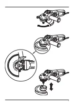
Depress the lock spindle pin (3).

Attention! Use the lock spindle pin (3) only if the spindle is at rest and 

the grinder is de-energized.

Swivel the wheel /spindle, until the lock spindle pin (3) is engaged. Tighten 

the clamping nut (14) firmly, using the wrench (16).

Attention! Prior to starting the grinder, verify that the wheel does 

not rotate freely between the bottom flange (11) and the clamping 

nut (14). 

Putting into operation

Check whether the data on the rating plate match with the real power 

supply voltage. The tool intended for 230 V~ may be also connected to 

220/240 V~. Check whether the plug type corresponds to the socket type.

Switching on

Push the switch (1) forwards, thus switching the machine on. If you depress 

the front switch button part (1), the switch will be arrested in the ON posi-

tion.

Switching off

By releasing the switch button (1), the switch will be returned to the initial 

position and the machine will be switched off. If the switch (1) is arrested 

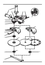
Description of the device

1 ............ Switch  

2 ............ Vent holes 

3 ............ Lock spindle pin 

4 ............ Revolutions pre-setting 

5 ............ Gearbox 

6 ............ Clamping collet 

7 ............ Spindle 

8a .......... Protective guard for grinding 

8b .......... Protective guard for cutting 

9 ............ Guide lugs 

10 .......... Clamping bolt 

11 .......... Bottom flange 

12 .......... Grinding wheel 

13 .......... Cutting wheel 

14 .......... Clamping nut 

15 .......... Clamping nut recess 

16 .......... Wrench 

17 .......... Additional handle (additional handle VIBRASTOP) 

18 .......... Hexagonal wrench dia. 4 mm

Depicted or displayed accessories need not necessarily become the integral 

part of delivery.

Double insulation

To ensure maximum safety of the user, our tools are designed and built to 

satisfy applicable European standards (EN standards). Tools with double in-

sulation are marked by the international symbol of a double square. These 

tools must not be grounded and a  two-wire cable is sufficient to supply 

them with power. Tools are shielded in accordance with EN 55014.

Use

The machine is designed for splitting, roughing and brushing metal and 

stone materials without the use of water. For cutting stone, a cutting guide 

is required.

The user himself is liable for any improper use.

Protective elements and their 

assembly 

The grinder may be used with mounted protective guard only!

Attention! Prior to handling the accessories, the power supply cable 

has always to be disconnected from the power source socket. 

Protective guard

Attention! The protective guard intended only and exclusively for 

work with the grinding wheels is the integral part of the standard 

angular grinder outfit. When cutting, the angular grinder has to be 

equipped by the protective guard intended for work with the cutting 

wheels; it can be purchased in the trade network under the order 

No. 00 763 301 for dia. 125 mm. Failing to use the guard for cutting, 

you run the increased risk of injury and in this case (non-use of the 

special guard for cutting) the company Narex is not liable anyhow for 

possible harm of health of the user or another person injured as the 

consequence of breach of the safety rules.

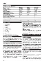
Technical Specification

Angular grinder

Model 

EBU 13-9 

EBU 13-11 

EBU 13-14 E

Voltage 

230–240 V 

230–240 V 

230–240 V

Mains frequency 

50–60 Hz 

50–60 Hz 

50–60 Hz

Power input 

900 W 

1 100 W 

1 400 W

Idle speed 

10 000 min

-1


10 000 min

-1


3 500–11 000 min

-1

Grinding/cutting wheel dia. max. 

125 mm 

125 mm 

125 mm

Additional handle VIBRASTOP 

 

 

Circumferential speed 

80 m/s 

80 m/s 

80 m/s

Work spindle thread 

M 14 

M 14 

M 14

Limits to interaction current 

 

 

Revolutions pre-setting 

 

 

Constant electronics 

 

 

Heat protection 

 

 

Weight without tool  

1.8 kg 

1.9 kg 

2.0 kg

Class of protection 

II /   

II /   

II / 

Содержание EBU 13-11

Страница 1: ...P vodn n vod k pou v n P vodn n vod na pou itie Original operating manual Instrucciones de uso originales p Pierwotna instrukcja obs ugi Eredeti haszn lati tmutat EBU 13 9 EBU 13 11 EBU 13 14 E...

Страница 2: ...jury hazard Cuidado Lea las instrucciones para reducir los riesgos de que se produzcan da os Uwaga Dla zmniejszenia ryzyka urazu nale y przeczyta niniejsz instrukcj Figyelem A vesz lyek cs kkent se rd...

Страница 3: ...3...

Страница 4: ...4 1 2 6 5 7 9 10 12 13 14 15 18 11 14 16 8a 8b 4 3 17...

Страница 5: ...5...

Страница 6: ...v no b Nepou vejte elektrick n ad kter nelze zapnout a vypnout sp na em Jak koli elektrick n ad kter nelze ovl dat sp na em je nebezpe n a mus b t opraveno c Odpojujte n ad vyta en m vidlice ze s ov z...

Страница 7: ...k razu u ivatele elektrick m proudem k Um st te pohybliv p vod mimo dosah rotuj c ho n stroje Ztrat te li kontrolu m e doj t k p e znut nebo p ebrou en pohybliv ho p vodu a va e ruka nebo pa e m e b...

Страница 8: ...230 V se sm p ipojit i na 220 240 V Zkontrolujte zda typ z str ky odpov d typu z suvky Zapnut Tla tko sp na e 1 p esu te zatla en m palce dop edu t m se stroj zapne Pokud budete tla it na p edn st tla...

Страница 9: ...ladovat v such m skladu bez vyt p n kde teplota ne klesne pod 5 C Nezabalen stroj uchov vejte pouze v such m skladu kde teplota neklesne pod 5 C a kde bude zabr n no n hl m zm n m teploty Recyklace El...

Страница 10: ...vajte spr vne n radie kto r je ur en pre vykon van pr cu Spr vne elektrick n radie bude lep ie a bezpe nej ie vykon va pr cu pre ktor bolo kon truovan b Nepou vajte elektrick n radie ktor nie je mo n...

Страница 11: ...kolostojacich v bezpe nej vzdialenosti od pracovn ho priestoru Ka d kto vstupuje do pracovn ho priestoru mus pou va osobn ochrann pom cky lomky obrobku alebo po koden pr slu enstvo m u odlietnu a sp s...

Страница 12: ...a Uvedenie do prev dzky Prekontrolujte i daje na v robnom t tku s hlasia so skuto n m nap t m zdroja elektrickej energie N radie ur en pre 230 V sa m e pripoji aj na 220 240 V Prekontrolujte i typ z s...

Страница 13: ...balen stroj je mo n skladova v suchom sklade bez vyt pania kde tep lota neklesne pod 5 C Nezabalen stroj uchov vajte iba v suchom sklade kde teplota neklesne pod 5 C a kde bude zabr nen n hlym zmen m...

Страница 14: ...not al low persons unfamiliar with the power tool or these instructions to operate the power tool Power tools are dangerous in the hands of untrained users e Maintain power tools Check for misalignmen...

Страница 15: ...l that is entering into the pinch point can dig into the surface of the material causing the wheel to climb out or kick out The wheel may either jump toward or away from the operator depending on dire...

Страница 16: ...t 1 the switch will be arrested in the ON posi tion Switching off By releasing the switch button 1 the switch will be returned to the initial position and the machine will be switched off If the switc...

Страница 17: ...lized service station au thorized correspondingly Storage Packed appliance may be stored in dry unheated storage place with tem perature not lower than 5 C Unpacked appliance should be stored only in...

Страница 18: ...y el cabello largo pue den ser atrapados por las partes m viles g Si se disponen de medios para conectar equipos de extracci n y recogida de polvo cerci rese de que stos est n bien conectados y de us...

Страница 19: ...est n agrietadas desgarradas o extremadamente gasta das y si los cepillos de hierro tienen los alambres flojos o partidos Si el accesorio o la herramienta se caen rev selos o monte un acce sorio no d...

Страница 20: ...a llave de seis bocas de un de 4mm 18 y revise el momento de compresi n de 3 5 Nm Agarradera adicional Laagarraderaadicional 17 sepuedeatornillarporlapartederechao izquier da de la caja de cambio 5 o...

Страница 21: ...ntre la brida inferior 11 y la tuerca de sujeci n 14 gira libre mente Puesta en funcionamiento Revise si los datos del r tulo de f brica son conformes a la tensi n real de la fuente de energ a el ctri...

Страница 22: ...dB A 104 dB A Imprecisi n de medici n K 3 dB A Utilice protectores auditivos El valor de vibraciones calculado que influye en las manos y brazos ah Typ EBU 13 9 EBU 13 11 EBU 13 14 E ah 20 25 m s2 20...

Страница 23: ...23 1 2 a RCD RCD 3 a 4 a 5 a...

Страница 24: ...o 24 a a...

Страница 25: ...25 EBU 13 9 EBU 13 11 EBU 13 14 E 230 240 230 240 230 240 50 60 50 60 50 60 900 1 100 1 400 10 000 1 10 000 1 3 500 11 000 1 125 125 125 VIBRASTOP 80 80 80 M 14 M 14 M 14 1 8 1 9 2 0 II II II...

Страница 26: ...N EN 55014 00 763 301 125 NAREX 8a 8b 6 9 8a 8b 10 3 5 6 10 4 18 3 5 17 5 5 VIBRASTOP EBU 13 9 VIBRASTOP 17 11 14 11 7 12 13 11 12 13 14 7 12 15 13 15 3 3 3 14 16 11 14 230 220 240 1 1 1 1 EBU 13 14 E...

Страница 27: ...1 EBU 13 14 E LpA 91 2 A 91 2 A 91 A LwA 102 A 102 A 104 A K 3 A ah EBU 13 9 EBU 13 11 EBU 13 14 E ah 20 25 2 20 25 2 4 11 2 K 1 5 2 EN 60745 60745 1 60745 2 3 2006 42 EC 55014 1 55014 2 61000 3 2 610...

Страница 28: ...narz dzi elektrycznych i troska o nie a Nie przeci ajcie narz dzi elektrycznych U ywajcie w a ciwych narz dzi kt re s przeznaczone do przeprowadzanej pracy W a ciwe narz dzie elektryczne b dzie lepiej...

Страница 29: ...latuj ce u amki powsta e podczas r nych czynno ci roboczych Maska chroni ca drogi odde chowe lub respirator musz by zdolne odfiltrowa cz steczki powsta e podczas waszej czynno ci D ugotrwa e nara enie...

Страница 30: ...e na tabliczce znamionowej zgadzaj si z rzeczywi stym napi ciem r d a energii elektrycznej Narz dzie przeznaczone do 230 V mo na pod czy r wnie do 220 240 V Nale y sprawdzi czy typ wtyczki od powiada...

Страница 31: ...punktu widzenia bezpiecze stwa Prace te musz by wykonane w specjalistycznym warsztacie elektrotech nicznym kt ry ma upowa nienie do wykonywania takiej pracy Sk adowanie Zapakowane narz dzie mo na sk...

Страница 32: ...zn lva b Ne haszn ljon olyan berendez st amelyet nem lehet kapcsol val ki s bekapcsolni B rmilyen elektromos szersz m amelyet nem lehet kapcsol val kezelni vesz lyes s meg kell jav tani c A szersz mot...

Страница 33: ...ez r nthatja n A szersz m szell ztettet ny l sait rendszeresen tiszt tsa A motor ventil tora besz vja a szekr nybe a port a felgy lemlett f mpor villa mos vesz llyel j r o A villamos szersz mmal ne do...

Страница 34: ...r s val di fesz lts g vel A szersz m 230 V os r szabad kapcsolni szabad 220 240 V os h l zatra Ellen rizze a dug t pus t meg e felel a dugaszalj t pus nak Bekapcsol Kapcsol nyom gombj t 1 h velykujjal...

Страница 35: ...li sz raz rakt rban t rolhat ahol a h m rs klet nem s llyed 5 C al A becsomagolatlan g pet csak olyan sz raz rakt rban t rolja ahol a h m r s klet nem s llyed 5 C al s amely nincs kit ve hirtelen h m...

Страница 36: ...x cz Narex s r o Chel ick ho 1932 CZ 470 01 esk L pa V robn slo Datum v roby Kontroloval Dne Raz tko a podpis Z RU N OPRAVY Datum P evzet P ed n Raz tko a podpis Prod no spot ebiteli Z RU N LIST 00 76...

Отзывы: