W415-1789 / C / 01.29.19
EN
26
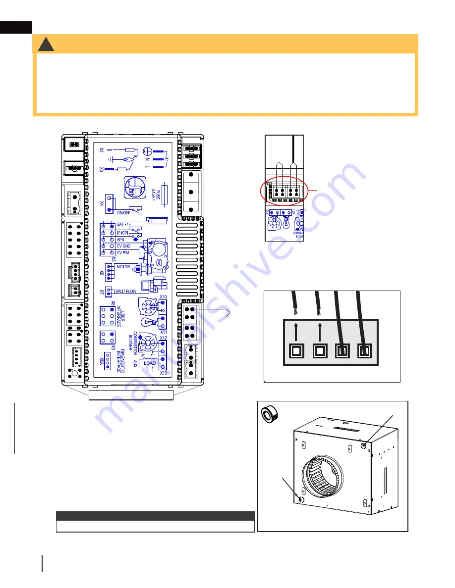
1. Unplug the blower / lamp terminal block on the SIT control
board, located in the appliance (see appliance manual for
details).
2. Determine the desired location of the wiring knockout
(Fig. 1)
,
and then remove the left or right knockout accordingly. Install
bushing (supplied) into knockout.
3. Loosen blower terminal screws and disconnect wires.
4. Disconnect the blower ground wire, which is screwed to the
base of the appliance.
5. Connect new armoured cable (not supplied) into the blower
terminal block and tighten the blower terminal screws.
6. Plug the blower / lamp terminal block back into the board.
7. If applicable, remove the 4 screws securing the decorative cover on the blower housing assembly and set
them aside
(Fig. 4, next page)
. Remove the decorative cover and set it aside.
Blower
Lamp
REMOVE WIRES TWO BLOWER
WIRES AS SHOWN
BLOWER/LAMP TERMINAL
BLOCK (TOP VIEW)
LAMP
COMFORT
FAN
BL
OWER
BLOWER/LAMP
TERMINAL BLOCK
LAMP
COMFOR
T
FA
N
APPLIANCE CONTROLLER
BLOWER
!
WARNING
• All wiring should be done by a qualified electrician, and must be connected and grounded in accordance with
local codes. In the absence of local codes, use the current CSA 22.1 Canadian Electrical Code in Canada or the
ANSI/NFPA 70-1996 National Electrical Code in the United States.
• All electrical wires must be strain-relieved and protected according to local codes and good installation
practices.
• You must used armoured cable for the installation of
DHC™ Plus
.
9.0 electrical information
9.1
wiring to SIT control board & remote control
note:
Ensure to ground new armoured cable to the ground screw.
Left Side
Knockout
Right Side
Knockout
Back View of Appliance
Fig. 1
x 1
Содержание DHCP-BK
Страница 35: ...EN W415 1789 C 01 29 19 35 12 0 notes...


