NAPCO iSecure Скачать руководство пользователя страница 62

62


All technical manuals are available in PDF format at 

tech.napcosecurity.com


Napco iSecure Security System


Common Error Codes / Troubles


E01 AC 

--

 Power Failure


This  trouble  will  occur  if  AC  power  is  not  present.    Make  sure 

system transformer is plugged into AC receptacle and check the 

circuit breaker, otherwise call installing company for service.


E01

-

89, E01

-

90, E01

-

91 and E01

-

92:  AC loss for the ISEC

-

WL

-

SIREN (#1 through #4)


E01

-

93, E01

-

94, E01

-

95 and E01

-

96:  AC loss for ISEC

-

WL

-

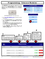
MODULE Takeover modules (#1 through #4). 


E02 

--

 Low Battery


If there has been a recent power failure, the battery may be par-

tially  depleted  and  must  be  recharged  by  the  Go

-

Anywhere 

Smart  Hub.    The  Go

-

Anywhere  Smart  Hub  performs  an  auto-

matic test of the battery every 24 hours, at which time the trou-

ble  will  clear  if  the  battery  has  been  recharged.    If  the  trouble 

does  not  go  away  in  24  hours,  call  installing  company  for  ser-

vice.


E03 

--

 Communication Failure


The system was not able to report to the central station.  If this 

is  due  to  a  temporary  interruption  in  the  radio  or  Internet  (or 

both)  service,  the  trouble  can  be  cleared  when  the  service  is 

restored by performing a Communication Test:  


1.


While  disarmed,  enter  your  User  Code  followed  by  EN-

TER.


2.


Answer  NO  until  "15"  (Telephone  Test)  appears  in  the 

window.


3.


Press YES to send a test signal to the central station.


4.


If the trouble continues, call installing company for service.


E04

-

NN 

--

 Wireless Transmitter Supervisory Failure


A problem has been detected  with a wireless transmitter.  Call 

installing company for service.


E04

-

(83

-

88) 

--

 Wireless Keypad Trouble Supervisory


A problem has been detected  with a  wireless keypad.  Call in-

stalling company for service.


E04

-

(89

-

92) 

--

 Wireless Siren Trouble Supervisory


A  problem  has  been  detected  with  a  wireless  siren.    Call  in-

stalling company for service.


E04

-

(93

-

96) 

--

 Wireless Takeover Module Trouble Supervisory


A problem has been detected with a takeover module.  Call in-

stalling company for service.


E05

-

(83

-

88) 

--

 Wireless Keypad Trouble Low Battery


E05

-

(89

-

92) 

--

 Wireless Siren Trouble Low Battery


E05

-

(93

-

96) 

--

 Wireless Takeover Module Trouble Low Battery


The battery in a wireless device is low and should be replaced.  

The replacement battery for the 

ISEC

-

WL

-

KEYPAD 

is CR123A 

(use one for standard battery life, use two for extended battery 

life).  The siren requires 4 alkaline C

-

size batteries.  If a low bat-

tery  is  indicated  for  a  takeover  module,  check  the  battery  or 

power supply  that is providing power to the module.    Warning:  

Replace  batteries  only  with  the  same  type  as  specified  above.  

Use of other types may present a risk of fire or explosion.  Nev-

er recharge or disassemble a battery, or dispose of in fire.  


E06

-

NN 

--

 Receiver Response Failure


Call installing company for service.  


E09

-

00 

--

 System Cold Start


For installer use only.  (This indication always appears when a 

system  "Cold  Start"  is  performed.    "Cold  Starting"  the  Go

-

Anywhere Smart Hub resets it back to its original "default" con-

dition, i.e. the state it was in when it left the factory).  


E10

-

NNN 

--

 Keypad Response Failure


Call installing company for service.  


E11

-

NNN 

--

 Keypad Tamper


The  Go

-

Anywhere  Smart  Hub  has  been  opened,  or  a  wall

-

mounted  keypad  has  been  opened  and/or  removed  from  the 

wall.    Call  installing  company  for  service  if  problem  cannot  be 

repaired.


E15

-

NNN 

--

 RF Transmitter Tamper


Wireless transmitter cover removed (NN = transmitter number).


E15

-

(83

-

88) ISEC

-

WL

-

TOUCH or ISEC

-

WL

-

KEYPAD (3

-

8) Tamper 


E15

-

(89

-

92) ISEC

-

WL

-

SIREN Tamper


E15

-

(93

-

96) ISEC

-

WL

-

MODULE Tamper 


Call installing company for service.


E16

-

NNN 

--

 Wireless Receiver Jam


A  problem  has  been  detected  with  the  wireless  receiver.    Call 

installing company for service.


E17

-

NNN 

--

 Receiver Tamper Condition


Call installing company for service.


E18

-

NNN 

--

 Keyfob Transmitter Low Battery


A  keyfob  transmitter  has  indicated  its  power  cell(s)  are  weak 

and  should  be  replaced.    The  4

-

button  ISEC

-

KEYFOB  uses  a 

3V Lithium coin cell battery (replace with type CR2032 or Dura-

cell DL2032 only).  The 1

-

button ISEC

-

PANIC uses two Energiz-

er 386 1.5V silver oxide cells (the unit will also flash its LED to 

warn of a low

-

battery).  

Warning: 

 Replace batteries only  with 

the same type as specified above.  Use of another battery may 

present a risk of fire or explosion.  Do not recharge or disassem-

ble battery, or dispose of in fire.  


E40

-

NNN 

--

 RF Self

-

Test Failure


A  wireless  motion  sensor  on  the  zone  indicated  has  failed  its 

automatic self

-

test routine.  Call installing company for service.


E41

-

NNN 

--

 Fire Trouble


A  problem  has  been  detected  on  the  fire  zone  indicated.    Call 

installing company for service.  


E42

-

NNN 

--

 CO Zone trouble


A  problem  has  been  detected  on  the  carbon  monoxide  zone 

indicated.  Call installing company for service.  


E51 

--

 Bell/Siren Trouble


There is a problem with the bell or siren.  Call installing compa-

ny for service.


E59

-

03 

--

 Ethernet failed to communicate


Call installing company for service.


E59

-

04 

--

 Ethernet poll/check

-

in failure


Call installing company for service.


E59

-

07 

--

 Wi

-

Fi failed to communicate


Call installing company for service.


E59

-

08 

--

 Wi

-

Fi poll/check

-

in fail


Call installing company for service.


E60

-

03 

--

 Radio failed to communicate


Call installing company for service.


E60

-

05 

--

 Radio Poll or Check in failure (RF only)


Call installing company for service.  


Содержание iSecure

Страница 1: ...Napco iSecure Security System All technical manuals are available in PDF format at tech napcosecurity com 1 NAPCO 2021 WI2240ALF 6 21...

Страница 2: ...It is subject to change without notice Companies names and data used in examples herein are fictitious unless otherwise noted Napco assumes no responsibility for incor rect information this manual ma...

Страница 3: ...Install the ISEC ZWAVE 40 Install the ISEC EXTANT KIT optional 41 Go Anywhere Smart Hub Icons 43 PROGRAMMING Programming Keypads Touchscreens 44 Programming Motion Sensors 45 Programming Glass Break S...

Страница 4: ...382LF Hub tamper in stallation instructions included All Kits support up to six 6 ISEC WL KEYPADs and or ISEC WL TOUCHs combined When the Go Anywhere Hub is connected to a network with a Wi Fi access...

Страница 5: ...gin Refer to the OI404LF card and enter your Dealer User ID Password and Radio ID iSecure LTE ID Click Submit D Click General Settings and in the Master Security Code field enter the Master Code also...

Страница 6: ...within 15 minutes of checkout With iSecure a new subscriber account will automatically be created A Dealer User ID and temporary Password will be emailed to you the dealer upon activation This tempora...

Страница 7: ...r the first time In the confirmation popup click Yes download to send all changes to the Go Anywhere Smart Hub Network MAC Unique Media Ac cess Control identifier assigned to the integral network inte...

Страница 8: ...to enable the IP path of the integral dual path radio communicator this selection is available depending on plan purchased Configuration Type Click the Configuration Type pull down to select the re po...

Страница 9: ...e iSecure Cloud Web Portal Note Radio will reboot after the successful download of new IP configurations IMPORTANT Some police and or fire departments require alarm permits contact each department do...

Страница 10: ...or 5AH battery not supplied observing polarity secure battery with Velcro strap 7 Remove the plastic protective film from the face of the Go Anywhere Hub STAND ALONE INSTALLATIONS If placing on a she...

Страница 11: ...s speakers or a mechanical bells this terminal and BELL Any self contained external siren requiring a 12V supply can be connected When connecting a mechanical bell it must be supervised using a 2 2k O...

Страница 12: ...o place 4 Drill the two keypad mounting holes four holes with the IBR TOUCH WL in the mounting surface When mounting to hollow drywall or similar surface we recommend using wall anchors or similar har...

Страница 13: ...security system keypad tap Keypad Only jump to step 6 To include video camera and Z Wave functions tap Full Functionality 4 5 Add the IBR TOUCH WL Tablet Kit 3 Only The steps below are the only steps...

Страница 14: ...dministrator account User ID and Password and tap Finish 10 Upon connection to the Internet based ac count for the iSecure system the resulting keypad shown in step 12 will be configured for the payme...

Страница 15: ...ON The ISEC MOTION is an advanced PIR sensor designed for use with Napco s wireless receivers The unit is powered by two sup plied 3 volt lithium batteries estimated battery life 3 years If bat tery v...

Страница 16: ...as a template to mark mounting holes on the wall The sensor must be in direct line of sight of all windows being protected Reliable detection cannot be expected around cor ners in other rooms etc For...

Страница 17: ...ector is mounted on the same wall as the glass point the tester at the opposite wall If the LED on the detector comes on for about 4 seconds when the tester is triggered the glass is within detection...

Страница 18: ...DESCRIPTION The ISEC DW XMITTER is a low profile window door transmitter designed for use in Napco iSecure wireless systems Used with the supplied magnet the transmitter functions as a window door se...

Страница 19: ...location to mount the ISEC SMOKE Note Mounting the ISEC SMOKE on foil backed wallpaper is NOT recommended because the radio range will be reduced The ISEC SMOKE is a high quality photoelectric smoke...

Страница 20: ...e correct zone on the Hub and that the correct report is sent to the central sta tion NOTE Smoke detectors are not to be used with detector guards unless the combination has been evaluated and found s...

Страница 21: ...utomatically exit this mode after 5 minutes Note If smoke is still present in the chamber after exiting Silence mode the detector will go into alarm again IMPORTANT Use proper polarity when installing...

Страница 22: ...eratures Also do not locate alarm in front of air conditioners heating registers or other locations where normal air circulation will keep smoke from entering the detector Installing smoke detectors i...

Страница 23: ...onitor and annunciate low battery Coding switches are not required or used in the ISEC HEAT Each transmitter is assigned a unique identification code number at the factory The transmitter is powered b...

Страница 24: ...ystem Test system with unit mounted If the system is monitored notify the central station of the impending test The rate of rise feature may be tested by a quick applica tion of heat from any convenie...

Страница 25: ...ta or Sanyo type 123A battery in its compart ment observing correct polarity Enroll the ISEC CARBON MON into the Hub before mounting During power up and status initialization both the green and red LE...

Страница 26: ...ss and hold the re cessed TEST button for approximately 2 seconds The detector will temporarily go into alarm and the red LED will illuminate b Within a few seconds the green LED will start to blink r...

Страница 27: ...e equipment manufacturer s doc umentation or contact the manufacturer s directly for more information about how the equipment can leak carbon monoxide into the premises Ensure all motor vehicles are n...

Страница 28: ...installation instructions in their entirety be fore installing the ISEC CARBON MON detector Leave these instructions with the owner user of the detector The ISEC CARBON MON is intended for use in ind...

Страница 29: ...detector indicates an end of life condi tion whichever comes first CO detectors are not a substi tute for designated life safety devices Napco does not war rant or imply in any way that a CO detector...

Страница 30: ...uit board no more than 45 degrees see Figures 1 and 2 to allow removal of batteries from the bottom circuit board 3 Slide the bottom battery out and away from the circuit board Figure 3 Top View of Bo...

Страница 31: ...to which transmitter is applicable The 6 digit RF ID code with checksum digit printed on the transmitter enter all numbers and or letters including lead ing zeros if any Aux 1 option and Aux 2 option...

Страница 32: ...t 3 Use the supplied double backed tape to secure the Tamper Magnet to the wall do NOT use any screws near electrical wiring that runs inside walls 4 At the wall outlet remove the wall cover plate scr...

Страница 33: ...on If RESET is not pressed the battery trouble will self restore in 4 hours if the battery voltage always remains above the minimum level during this time TERMINAL DESCRIPTIONS Configure all inputs an...

Страница 34: ...through JP12 for ZONE 8 Each zone 1 8 is assigned to terminals Z1 through Z8 respectively Notice each jumper block labeled JP5 through JP12 contains vertical 4 pins FIRE top two pins Selected zone rep...

Страница 35: ...UMPER ZONE 1 FIRE CO BURG SET JUMPER ZONE 7 FIRE CO BURG SET JUMPER ZONE 8 FIRE CO BURG P2 1 2 3 4 5 6 BAT BAT DC DC 12 18VAC TRANSFORMER Control panel power or auxiliary power supply FIRE CO BURG ZON...

Страница 36: ...zone 7 FIRE PR Connects to the positive terminal of the two wire smoke sensor Z8 Connects to the negative terminal of the two wire smoke sensor zone 8 Connect the 2 wire smoke detectors to the Go Anyw...

Страница 37: ...MOD INSTALLATION If the Go Anywhere Smart Hub enclosure is not already open open the enclosure as directed on page 10 step 3 Remove all A C and battery power and install the ISEC 2WF MOD into the iSe...

Страница 38: ...t secure the Go Anywhere Hub motherboard PCB to the front housing See the arrows in Fig 2 for screw locations 8 With the ISEC WIFI PC board in hand connect the small Antenna Board plug to the ISEC WIF...

Страница 39: ...orks pull down find and select the SSID name of the customer s network Upon selection the Security Type and Selected Network fields will automatically populate Type the Password of the customer s Wi F...

Страница 40: ...our body or clothing Use a grounded wrist strap or touch an unpainted grounded metal object If replacing an older version of the ISEC ZWAVE first down load the latest version of the Z Wave firmware at...

Страница 41: ...e front LED Faceplate to the front housing 4 Remove the LED Faceplate From the front of the housing pull out the LED Faceplate to remove 5 On the inside of the LED Faceplate remove the screw that secu...

Страница 42: ...lose the two parts of the Hub housing routing the cable out the rear access door see Fig 9 Be sure not to crimp the wire between the PCB and the housing Closing the two parts of the Hub housing will r...

Страница 43: ...Receiver trouble due to excessive radio noise in area Try relocating the Smart Hub Otherwise call for service Rapid Flicker Transmissions in progress Flashing 900MHZ peripheral download Status Off No...

Страница 44: ...he ISEC WL TOUCH press and hold the appropriate FIRE AUX or PANIC button respectively see the User s Guide for details By default Emergency Buttons are ena bled for all keypads to disallow their use s...

Страница 45: ...R FUNCTION Select Instant or Interior When armed STAY usually when sleeping and you want the motion to ignore movement within the home select Interior If you want the sensor to immediately trigger an...

Страница 46: ...it sensor ID for the device 4 DESCRIPTION Type the sensor descrip tion you wish to appear on the keypad display AREA Default 1 See the key pad Operating Guide for the definition of Area SENSOR FUNCTIO...

Страница 47: ...or For example use for an interior door that will be in use when armed STAY but protected when armed AWAY Instant Allows for an immediate alarm when activated providing instant protection while you or...

Страница 48: ...N Type the sensor descrip tion you wish to appear on the keypad display SENSOR TYPE Select Smoke Sensor SENSOR FUNCTION Smoke is au tomatically se lected when Smoke Sen sor is selected as the SENSOR T...

Страница 49: ...on the keypad display SENSOR TYPE Select Heat Sensor SENSOR FUNCTION Heat is auto matically select ed when Heat Sensor is se lected as the SENSOR TYPE SENSOR ID Type in the 7 digit sen sor ID for the...

Страница 50: ...or DESCRIPTION Type the sensor descrip tion you wish to appear on the keypad display SENSOR TYPE Select Carbon Monoxide SENSOR FUNCTION CO Alarm is automatically selected when Carbon Mon oxide is sele...

Страница 51: ...the following Instant Allows for an immediate alarm when the panic button is pressed providing instant protection 24Hr Zone Audible Provides protection at all times whether or not the system is armed...

Страница 52: ...e Select to disable the designated key Key 3 and or Key 4 Panic Pressing the designated key causes the siren to sound and sends a panic report to the central station Instant Pressing the designated ke...

Страница 53: ...in any Area ISEC WL SIREN Wireless Siren TYPE Sirens can be powered by an AC power supply plugged into a 120VAC unswitched wall outlet or with batteries Select the power type used by your siren NAME...

Страница 54: ...ired zone to the RF ID of the supervised 900MHz wireless zone up to 8 zones for each ISEC WL MODULE In the TAKEOVER screen shown below for the Takeover Module added previously program each column as d...

Страница 55: ...umn 3 To add a new Code click in a blank USER CODES field and enter the new User Code up to 6 digits To erase or change an existing Code simply clear or re enter the User Code 4 Add a check to either...

Страница 56: ...ng to establish a connection if this code is forgotten the Master Security Code of the particular Go Anywhere Hub can be used in its place Dealer Keypad Programming Code This code is left blank in the...

Страница 57: ...at you wish to be used in text and email notification messages to help you identify the iSecure system installation Video Security Z Wave Remote Access Check to enable access to each service from the...

Страница 58: ...can also be configured to allow Wi Fi con nections to only specific MAC Addresses Displays the MAC Address of the Go Anywhere Hub in an easy to copy field should it be needed Users Displays the USER I...

Страница 59: ...sor within the Go Anywhere Hub that controls the radio communications between the Hub and the wireless de vice s Other iSecure Cloud Web Portal Screens cont d RadioHardware Version refers to the versi...

Страница 60: ...relocate the Go Anywhere Smart Hub or the device so they are in closer proximity E 05 NN Transmitter Low Battery When an RF device has a weak battery an error E 05 appears The NN is a two digit number...

Страница 61: ...top as shown in the image Note Never use the jumper position N A Use hearing protection siren is rated at 85dBA Do not apply AC power when rear cover is open 1 Remove AC and batteries 2 Remove jumper...

Страница 62: ...h the same type as specified above Use of other types may present a risk of fire or explosion Nev er recharge or disassemble a battery or dispose of in fire E06 NN Receiver Response Failure Call insta...

Страница 63: ...TER When the test is initiated data is transferred back and forth be tween the keypad and Hub When finished the signal levels of both the keypad and Hub are displayed and a beep is heard in the sequen...

Страница 64: ...Secure system might be interfering with the system to be installed the ISEC WL KEYPAD can be used as a scanner to scan for the presence of other nearby iSecure radio signals and determine if the nearb...

Страница 65: ...unication link between the Hub and the ISEC WL TOUCH keypad was interrupted If Out of System this field will count down AutoEnroll This feature is a quick and easy way to enroll wireless devices into...

Страница 66: ...w E02 00 will appear in the display indicating a low battery condition Allow 24 hours for the battery to recharge DISPLAY SYS TRBL Displays all system error codes troubles LOW BAT TERY AC POWER LOSS e...

Страница 67: ...pertinent information where necessary depending upon the event TO ARM IN 1 4 HRS Use this function to a delay programmed auto arming up to 4 hours 15 minutes or b initiate auto arming in 4 hours 15 mi...

Страница 68: ...scribed below tap Config ure otherwise tap Continue to App to return to the Home Screen or Test Again to repeat the test See page 13 for step by step instructions to help guide you through the Wiz ard...

Страница 69: ...1 3 5 7 10 15 and 20 minutes BSSID used to LOCKDOWN IBRIDGE Tap to enter a new broadcast SSID named BSSID in this menu to be stored in the touchscreen s memory to be used by default when the touchscre...

Страница 70: ...then connect power to the camera Do you wish to proceed with Wire less Camera Configuration 1 The camera must be powered and wirelessly con nected to the network before proceeding 2 Tap Yes to procee...

Страница 71: ...wish to disallow customer changes to the home automation Z Wave system unchecking disabling this setting disables the User Settings menu feature named Automation Management z wave Converse ly check t...

Страница 72: ...hours with network connection 32 hours ISEC KIT2 Battery Standby Hours 12V 4AH battery No network connection 25 hours with network connection 24 hours 12V 5AH battery No network connection 32 hours w...

Страница 73: ...RT HUB In cludes up to 80 wireless zones in 1 or 2 discrete Areas with keypad bus and other optional con nections Kits with the suffix V use the Verizon network A use the AT T network IBR TOUCH WL Sma...

Страница 74: ...s re ceivers The ISEC MOTION is powered by two supplied 3 volt lithium batteries estimated battery life 3 years When battery voltage drops below normal a low battery report will be sent to the re ceiv...

Страница 75: ...Wireless Siren Mounting Template Slide Screw Use with battery powered units only Magnet 1 5 8 Align this centerline with Wall Socket 7 16 Magnet Screws 2 Use with battery powered units only Center Lin...

Страница 76: ...76 All technical manuals are available in PDF format at tech napcosecurity com Napco iSecure Security System Notes...

Страница 77: ...rews 2 Use with battery powered units only Center Line of Wall Socket 5 1 4 Screw Hole Tab Align this centerline with Wall Socket This template shows the unit plugged into the bottom receptacle but ei...

Страница 78: ...78 All technical manuals are available in PDF format at tech napcosecurity com Napco iSecure Security System ISEC WL MODULE Takeover Module Wiring Diagram...

Страница 79: ...Napco iSecure Security System All technical manuals are available in PDF format at tech napcosecurity com 79 iSecure Hub Wiring Diagram LA3550A3...

Страница 80: ...he product Seller s warranty as hereinabove set forth shall not be enlarged diminished or affected by and no obligation or liability shall arise or grow out of Seller s rendering of technical advice o...

Отзывы: