


Napco iSecure Security System
All technical manuals are available in PDF format at
tech.napcosecurity.com
41
Install the ISEC
-
EXTANT
-
KIT (optional)
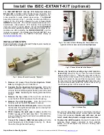
The
ISEC
-
EXTANT
-
KIT Internal LTE Extended Antenna
Bracket Kit
is installed inside the iSecure Go
-
Anywhere Hub
to permit the connection of an external LTE antenna to im-
prove reception in weak cellular signal areas. This
Bracket
assembly, pictured in Fig. 1, provides an alternate SMA con-
nection to the LTE radio, allowing the use of Napco
SLE
-
ANTEXT
antenna kits. The remote
-
mounted antenna is a du-
al
-
wideband, indoor/outdoor LTE antenna that significantly
improves cellular reception (
Note:
Mount the
SLE
-
ANTEXT
antenna before performing these instructions to allow its im-
mediate use after installing the
ISEC
-
EXTANT
-
KIT
and the
radio is re
-
powered). For details about the SLE
-
ANTEXT, see
WI2230, available from the NAPCO Technical Library at
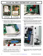
INSTALLATION STEPS
Bracket installation requires flat and Phillips head screwdrivers
and a cable zip tie (supplied).
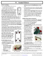
1.
Remove AC power from the Go
-
Anywhere Smart
Hub
by unplugging the AC transformer.
2.
Separate the Go
-
Anywhere Hub housing
. With a flat
head screwdriver, push in the two tabs at the bottom to
unhook, then carefully separate the two parts of the Hub
housing.
Note:
Separating the housing disconnects the
battery.
3.
Remove the top screw
at the top of the unit that se-
cures the front LED Faceplate to the front housing.
4.
Remove the LED Faceplate
. From the front of the
housing, pull out the LED Faceplate to remove.
5.
On the inside of the LED Faceplate
, remove the screw
that secures the
right side
light pipe (when viewing from
the rear) as shown in Fig. 2.
6.
While keeping the light pipe in place
, position the
Bracket
on top of
the light pipe boss. Re
-
install the
screw removed in step 5 and install an additional screw
as shown in Fig. 2.
7.
Connect the Antenna (SMA female) cable
end to the
male threaded end of the Bracket (see Fig. 3). Route
the cable through the Hub housing.
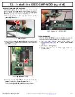
8.
Remove (by hand) the existing very small main An-
tenna Plug
(shown in Fig. 4) from the radio PC board
socket shown in Fig. 5. Tape the plug end of the re-
moved cable to the inside of the enclosure to prevent
inadvertent contact to any electrical components. Align
the new plug from the
Antenna Bracket
assembly over
the open radio socket (select the correct socket in Fig.
5) and press gently until it snaps into place.
Be sure the plug freely rotates but remains connected.
If this plug should disconnect, simply insert and press
firmly until connected.
Handle wire with care; do not
twist, create sharp bends or apply excessive force
.
9.
Replace the LED Faceplate
. Be careful to ensure both
Antenna Plugs remain connected to their sockets.
Note:
Do not overtighten top screw or housing cover
could distort.
Fig. 4: Antenna Plug
Fig. 1: Antenna Bracket Assembly ("Bracket")
Fig. 2: Two views of rear LED Faceplate: Secure Bracket to
right side with two screws (arrows) on top of light pipe.
Fig. 3: Connect the cable to the Bracket.


