background image

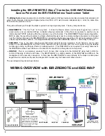
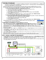
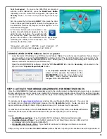
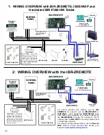
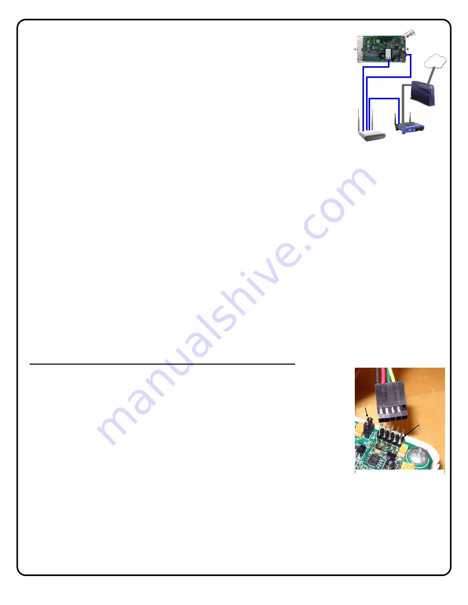
STEP 4:  WIRE IBR-ZREMOTE NETWORK CONNECTIONS TO  

ISEE-WAP AND ROUTER 


Using 

three 

(3) standard CAT5 network cables, connect... 



...one end of the 

1st cable

 into another open LAN socket on the ISEE-WAP, the other end into 

the IBR-ZREMOTE receptacle labeled "

ETHERNET

" (located on the front next to the local 

download jack).   



...one end of the 

2nd cable

 into another open LAN socket on the ISEE-WAP, the other end into 

the other IBR-ZREMOTE receptacle located on the right side of the IBR-ZREMOTE (as shown 
in the diagram on page 4).   



...one end of the 

3rd cable

 into an open LAN socket on the customer's existing router, the other 

end into an open LAN socket of the ISEE-WAP.  
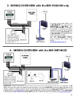
Note:

  See the diagram "

2:  WIRING 

OVERVIEW with the IBR-ZREMOTE

" on page 17 for connections without an ISEE-WAP 

when no wireless tablets and/or iSeeVideo cameras are wanted. 


Note:  Customer's router 

must 

support DHCP

.  Reconnect the battery connection and power the control panel.  Wait 

two (2) minutes for all devices to fully power and complete their network connections.  Remember, the panel configuration 
jumper is set to 

CONFIG

 mode, so the keypads will power up and display "

OUT OF SYSTEM

". 


STEP 5: CONFIGURE THE IBR-ZREMOTE KEYPAD ADDRESS & KEYPAD TYPE 

Note:

  The IBR-ZREMOTE requires a unique keypad address on the Napco keypad bus.  By default, the IBR-

ZREMOTE is configured as keypad address #1 and as a Napco "Classic Keypad".  If not changing the keypad address 
and/or keypad type, move the panel 

CONFIG

 jumper back to 

NORM

, and go to step 7. 


If the IBR-ZREMOTE is going to be set as keypad address #1 and set as a Napco "Classic" keypad, you will only have to 
set the keypad addresses for any other additional conventional wired keypads connected to the control panel.  Configure 
each additional keypad as you normally would by moving the configuration jumper to 

CONFIG 

and entering Keypad 

Configuration Mode by pressing 

1 1 1 2 3 FUNCTION

 (

or MENU

) on each alpha keypad.  


 5A. 

The IBR-ZREMOTE 

Keypad Address 

and 

Keypad Type 

can be configured in one of three ways: 


• 

Using a configuration keypad (such as a Napco GEM-RP1CAe2 or GEM-K1CA) to configure 
the IBR-ZREMOTE (recommended method) 

• 

Using an app on your iPhone, iPad or Android device to configure the IBR-ZREMOTE 

• 

Using the IBR-ITAB Tablet to configure the IBR-ZREMOTE 


If the IBR-ZREMOTE 

Keypad Address 

and/or 

Keypad Type 

needs to be changed, please use one of the three methods 

below. 


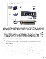
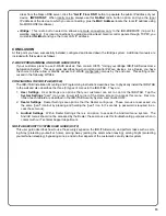
USING A CONFIGURATION KEYPAD TO CONFIGURE THE IBR-ZREMOTE

 (Recommended Method) 


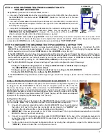
A model GEM-RP1CAe2 or GEM-K1 keypad (henceforth called a "configuration keypad") can 
be plugged into the IBR-ZREMOTE "Header Socket" receptacle (marked "

J3

" on the PC 

board; see the image at right).  When connected, the IBR-ZREMOTE can be configured 
exactly the same way as a physical Gemini keypad.  Connect one end of the provided RCM-
PROGCABLE keypad bus cable to the Gemini keypad, then connect the other end to the IBR
-ZREMOTE circuit board receptacle marked "

J3

" (insert the plug with the black wire adjacent 

to jumper J4; the plug keying tab faces away from the unit). 


Configuration Procedure 

Use the "configuration keypad" to program the IBR-ZREMOTE 

Keypad Address 

and 

Keypad 

Type 

as follows.  

Note: 

 The "configuration keypad" must be addressed as keypad #1. 


1.  Ensure both jumpers marked 

J2 

and 

J3

 on the IBR-ZREMOTE circuit board (located at 

the bottom right next to the blue bus connector) are set closer to the "

4-WIRE

"   text 

printed on the circuit board (this is the default shipping configuration).  

2. 

IMPORTANT:

  Remove jumper 

J4 

on the " Z-Wave circuit board" (the top circuit board located within in the IBR-

ZREMOTE housing, next to silver battery). 

3.  Connect one end of the special keypad bus cable (RCM-PROGCABLE) to the back of the configuration keypad and 

connect the other end to the IBR-ZREMOTE "Header Socket" receptacle (marked "

J3

" on the PC board as shown in 

the image above). 

4.  Put the control panel into Keypad Configuration Mode by moving the configuration jumper to the bottom two pins 

("

CONFIG

" ), located inside the control panel enclosure. 


CUSTOMER ROUTER 

(Wireless or Wired-only)


BROADBAND 

MODEM


Internet 

ISEE-WAP 

(

(

(


(1) CAT5 Ethernet 
Connection 

(2) CAT5 Ethernet 

Connection 

(3) CAT5 to Router 

IBR-ZREMOTE


(

(

(


RCM-PROGCABLE  plugs into the 

"Header Socket" (J3) 

Jumper J4 also shown. 

J4 

J3 

Содержание iBridge Suite

Страница 1: ...00 645 9445 For Technical Service 800 645 9440 or visit us at http tech napcosecurity com Note Technical Service is for security professionals only Publicly traded on NASDAQ Symbol NSSC NAPCO 2015 Z R...

Страница 2: ...o to www ibridgeonline com to access your existing account or register for a new account Device apps are available for iPhones iPads and Android devices from their respective apps markets Remote Contr...

Страница 3: ...the iBridge mobile app using the iBridge Wi Fi service provided by the IBR WIFI MOD NOTE A remote service subscriber account on www ibridgeonline com is NOT required for LOCAL ONLY control For remote...

Страница 4: ...ess to the IBR ZREMOTE and the TCP IP network and also provides Wi Fi for local control using the iBridge mobile app running on iPhones iPads or Android devices The ISEE WAP is not required if not usi...

Страница 5: ...nd mount the charging plate as described in WI1944 or just connect the power adapter to the charger plate observing polarity and power the IBR ITAB to continue STEP 2 CONFIGURE THE CONTROL PANEL The a...

Страница 6: ...eypad Assignment select the keypad address you will set up in step 5 for the IBR ZREMOTE and change the keypad address Type to RCM and add the keypad into the Area see image at right select EZ Arm 6 c...

Страница 7: ...g a configuration keypad such as a Napco GEM RP1CAe2 or GEM K1CA to configure the IBR ZREMOTE recommended method Using an app on your iPhone iPad or Android device to configure the IBR ZREMOTE Using t...

Страница 8: ...d select KEYPAD MODE After putting the control panel into Keypad Configuration Mode it normally takes up to 40 seconds for the keypad on the iBridge APP to go out of system The keypad will display 01...

Страница 9: ...et to go out of system The keypad will display 01 Out of System RCM MODULE IMPORTANT After the display reads XX OUT OF SYSTEM you MUST stop and wait for the IBR ZREMOTE components to reset and prepare...

Страница 10: ...n is now placed in the Please enter pass word popup as shown Tap OK The following warning popup appears Tap Yes and the following User Settings menu appears Tap Tablet then tap Connection The followin...

Страница 11: ...onnect to the ISEE WAP with this unique SSID and this unique Key Proceed as follows Choose the Tablet Connection SSID At the Connection Settings menu that appears shown at right tap 2 Tablet Connectio...

Страница 12: ...y IP address Tap to select each camera one at a time and tap Lock to lock the camera Exit when complete Lock Down the ISEE WAP In the Connection Settings menu tap 4 Lock Down IBRIDGE ISEE WAP Locking...

Страница 13: ...connected with the correct ISEE WAP press the Back Power Button repeatedly until the Home Screen appears then press the Security button A screen with your arming choices ap pears Arm the system by fir...

Страница 14: ...ew a list of User IDs as well as manage both your cameras and keypads registered to your dealer account Note For forgotten passwords your customer must click the Forgot your password link at www ibrid...

Страница 15: ...1944 CONFIGURING THE IBR ITAB WI1944 The IBR ITAB Installation Mounting and Programming instructions describes how to physically install the IBR ITAB to the wall and also describes the three 3 types o...

Страница 16: ...cient for the 380mA required for the IBR ITAB HW use a separate UL Listed Security and Signaling power limited 12V power supply Be sure the negative terminals of the power supply and control panel are...

Страница 17: ...STANDARD KEYPAD Internet RED BLACK GREEN YELLOW IBR WIFI MOD CONTROL PANEL CAMERAS IBR ITAB IBR WIFI MOD Wireless Panel Interface communicates between Internet Gemini Control Panel through the 4 wire...

Страница 18: ...18 NOTES...

Страница 19: ...to a different outlet so that computer and receiver are on different branch circuits If necessary the user should consult the dealer or an experienced radio television technician for additional sugges...

Страница 20: ...on purporting to act on its behalf to modify to change or to assume for it any other warranty or liability concerning its products In no event shall NAPCO be liable for an amount in excess of NAPCO s...

Отзывы: