Chapter 2. Preparation and Installation
HR8 Motor User Manual
2-9
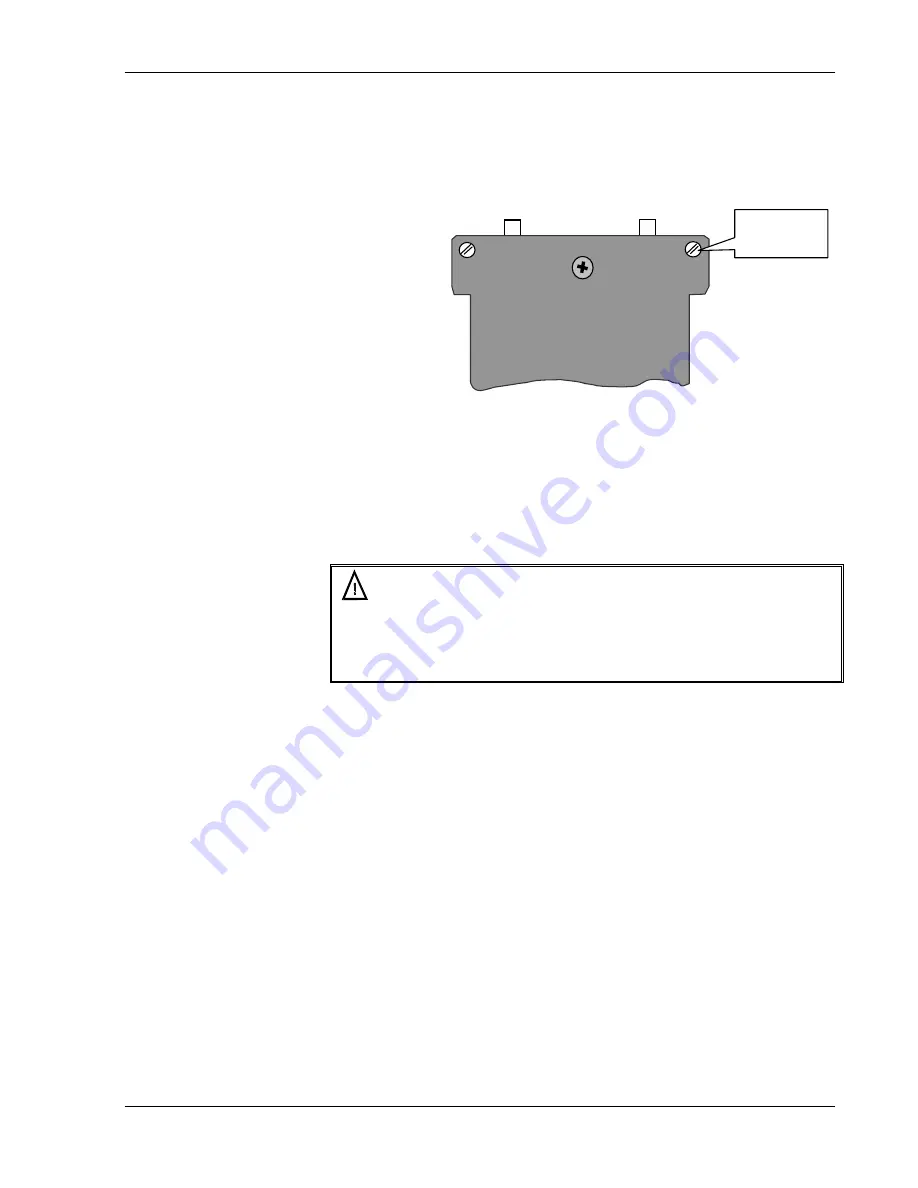
4. Release the preload setting screws: using again the 3mm flat
screwdriver, turn both screws
clockwise
until the turn is
completed and the slot is in the position illustrated below. The
motor is now preloaded against the ceramic drive plate.
Released
position
Figure 2-7: Released Position
5. Ground the motor according to the following section.
2.2.3 Motor
Grounding
Warning !!!
Be sure to ground the motor to the electrical network ground
(according to the following instructions) before operating the
motor.
1. Prepare a grounding wire and terminal connection with the
following specifications:
!
Terminal diameter - for an M3 screw
!
Wire diameter - minimum 18 AWG
!
Wire length - maximum of 2 meter
2. Open the motor ground screw (figures 3-5 & 3-6) and connect
the Ground connection prepared in step-1.
3. Secure the terminal between the two lock washers.
4. Connect the other end of this cable to the electrical network
ground.
5. Connect the motor to its driver according to the instructions
given in the following section.


