background image

 52

à 

go back to contents 

10.  Software STEVE


Digitally staining

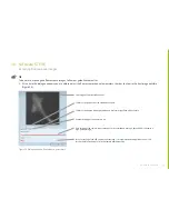
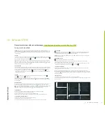
How to digitally stain cells with STEVE

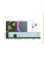
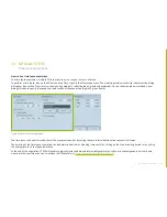
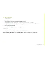
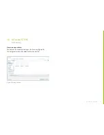
1.  Choose a meaningful slice on the 2D visualization panel (left side).

• 

Dragging the mouse up to down (left click pushed) on the 2D visualization panel or by moving the Slices slider.

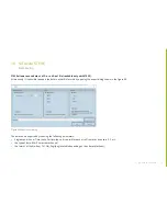
2.  Pick a new stain.

• 

Click on the + button.

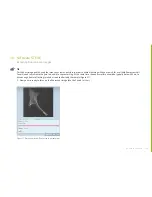
3.  Choose a name (optional).

• 

Click on the black-gray line edit form.

• 

Write down the name in the line text input.

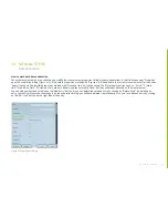
4.  Choose a color.

• 

Click on your desired color.

• 

Option: drag the mouse to have a more precise vision of the color that you could select.

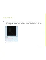
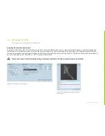
5.  Go to the 2D visualization panel and draw.

• 

Click and/or drag the mouse on your desired region of interest. The pixels under your cursor are glowing in the panel view. When you 

 release the mouse, we compute the stain from your selected pixels.

• 

Option: You could zoom in on the 2D visualization panel by wheeling the mouse.

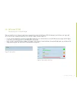
6.  Now the stain is represented in the panel view and superimposed on the 2D visualization panel.

• 

Option: you could change the weight of the colored image on the 2D visualization panel by moving the Overlay slider.

Содержание 3D Cell Explorer-fluo

Страница 1: ...3D Cell Explorer fluo User Manual...

Страница 2: ...scription Main Features 8 Typical Field of Applications 9 3D Cell Explorer fluo terminology 10 CoolLED illumination system terminology 11 4 Technical Specifications Sheet 12 5 Computer Technical Speci...

Страница 3: ...uo Class I laser For measurements the 3D Cell Explorer fluo uses a Class I laser A Class I laser is harmless for your eyes under any circumstances and thus does not require laser safety goggles when p...

Страница 4: ...highly flammable do keep it away from fire or potential sources of electrical sparks and use it in a well ventilated room when using it for cleaning the 3D Cell Explorer fluo or other measures 6 The...

Страница 5: ...Source being impaired The DC power supply unit should be inspected periodically throughout the lifetime of the system To clean the exterior of the Light Source use a slightly dampened cloth with a sim...

Страница 6: ...microscope Please be aware that the warranty expires if you remove the covers 8 Keep the instrument clean and do not contaminate the optical elements when wiping away the dust on the instrument It is...

Страница 7: ...the first instance remove any loose debris with an air duster aerosol or rubber blower 5 Finger prints or other liquid type contaminants should be removed using standard lens cleaning procedures Do n...

Страница 8: ...tation 474 nm Emission 515 nm TritC Excitation 554 nm Emission 595 nm Cy5 Excitation 635 nm Emission 730nm Note TritC and Cy5 excitation filters are exchangeable on channel 3 Please refer to the follo...

Страница 9: ...information with chemical information for specific protein drug tracking protein localization and mapping long term over a week live cell imaging in 3D at high temporal resolution 1 image every 2 sec...

Страница 10: ...ion Head USB 2 0 slot Power switch Power supply plug port BNC cable plug port Hi grade stage for sample screening Z knob for optical focusing Cell container interface XY knob for sample screening Came...

Страница 11: ...mination system terminology CoolLED illumination system front view CoolLED illumination system rear view CoolLED illumination system side view 1 Liquid Light Guide LLG CoolLED illumination system Top...

Страница 12: ...typical 70 at 545 nm Dark Noise typical 6 6 e Dynamic Range typical 73 7 dB Microscope Objective MO Dry objective 60x magnification NA 0 8 Illumination Source Class I laser low power 520 nm sample ex...

Страница 13: ...erating System 64 bit versions of Windows Vista 7 8 or 10 Updated drivers you need to have the latest Nvidia Graphics Card drivers USB 3 0 drivers and fully updated Windows Operating System In additio...

Страница 14: ...contains the following 1 the 3D Cell Explorer fluo 2 1 USB 2 0 cable 3 1 USB 3 0 cable 4 1 power supply 5 1 power cable 6 1 cleaning set 7 WEEE certificate 8 protective cap for the MO and 9 protective...

Страница 15: ...ht Source 12 DC Power Supply 13 IEC Power Cable 14 1 USB 2 0 cable 15 liquid light guide LLG protected with red vinyl caps use the red vinyl caps to protect both end of the LLG when not in use 16 3 ho...

Страница 16: ...spots in the image below Never lift the 3D Cell Explorer fluo by holding the camera go back to contents WARNING Nanolive does not bear the damage produced by wrong handling of the 3D Cell Explorer fl...

Страница 17: ...e original packaging or keep it for storage or return of the instrument to the manufacturer Remove the disposable plastic foil and red vinyl protective cap 6 Start up Installation and setup Disposable...

Страница 18: ...ntents 3 Install the CoolLED Illumination System on a stable flat horizontal and firm workbench Lift the CoolLED Illumination System carefully out of the box together with its accessories 6 Start up I...

Страница 19: ...Install the excitation filters on the CoolLED Illumination System Place the little drawers containing the excitation filters in the dedicated slots Mind the order and the direction 6 Start up Installa...

Страница 20: ...e as shown below Figure 2 Use an Allen key n 1 5 to secure the LLG in place Once the screw is in mechanical contact with the LLG header gently apply an extra force to make sure the LLG is maintained i...

Страница 21: ...below Place the light source close to the 3D Cell Explorer fluo in order to avoid any strain on the LLG or too short radius turns Ensure that the Light Source sits upright on a flat surface and keep...

Страница 22: ...the LLG to the 3D Cell Explorer fluo Remove the red cap from the LLG from the other end Figure 5 Insert the LLG as far as it can go into the injection head on the 3D Cell Explorer fluo as shown below...

Страница 23: ...place Bring the 3 screws first in mechanical contact without effort one after the other Gently apply some force to keep the LLG in place one after the other Please be aware that any damage made to th...

Страница 24: ...ion system and the 3D Cell Explorer fluo Do not stretch squeeze or bend the LLG excessively 6 Start up Installation and setup Important Note Short term bending radius Rshort 40 mm Long term bending ra...

Страница 25: ...r lead to the DC power supply Figure 11 Plug the CoolLED illumination system USB 2 0 cable into the USB 2 0 port on the top of the CoolLED illumination system and connect it to one of the USB slots on...

Страница 26: ...nnect the power cable Connect the power cable supplied to a convenient socket plug in the IEC connector into the DC power supply and switch the power on at the socket Computer USB 2 0 USB 2 0 LLG Powe...

Страница 27: ...ly Then plug the Nanolive power supply into the power port Plug the Nanolive USB 3 0 cable into the USB 3 0 port on the side of the 3D Cell Explorer the camera tightly screw the locks and connect it t...

Страница 28: ...our 3D Cell Explorer fluo the delivery note or on the back of the quick start guide Download and install STEVE Start STEVE while still connected to the internet The user s manual and important informa...

Страница 29: ...ion system a power b USB2 0 c USB3 0 d BNC and e light guide 2 Secure the sample stage of the 3D Cell Explorer fluo in top position 3 Protect the Microscope Objective with its dedicated red vinyl cap...

Страница 30: ...e sample stage Before moving the 3D Cell Explorer fluo please ensure that the sample stage is blocked in top position by using the z screw to avoid damaging the Microscope Objective as shown in the pi...

Страница 31: ...through the sample stage aperture Push it until it leans on the knurled part of the MO go back to contents 7 Handling Correct handling of the 3D Cell Explorer fluo Instructions on how to protect the...

Страница 32: ...gurations involving sharp angels or kinks or contact with sharp or pointed objects Light guide breakage will result in diminished light output Figure 16 Any inadvertent cut or puncture to the outer wa...

Страница 33: ...the places provided for lifting carrying and holding go back to contents 7 Handling Correct handling of the 3D Cell Explorer fluo Instructions on how to carry the 3D Cell Explorer fluo correctly Once...

Страница 34: ...FluoroDish Thanks to extremely low light exposure and compatibility with cell culture accessories the 3D Cell Explorer fluo is suitable for long term live cell imaging We have designed a Sample Prepar...

Страница 35: ...ake a fresh and clean swab soaked in ethanol or isopropanol and with out pressure swipe the contaminant away from the center of the optical element Use a fresh side of the swab after each contact with...

Страница 36: ...36 go back to contents 9 Cleaning Procedure for optical elements Figure 19 Figure 20 go back to contents...

Страница 37: ...rt your acquisitions set up STEVE with the correct fluorescence filter configuration as shown below The 3D Cell Explorer fluo is delivered with the options FITC green TRITC orange and DAPI blue or Cy5...

Страница 38: ...of interest Single shot acquisition acquire a single 3D frame Time lapse acquisition acquire multiple 3D frames in a range of time Load a measurement le vol Save a 3D or 4D measurement le vol To save...

Страница 39: ...in a multi channel image Transport Control Buttons Area Sliders Area Digital Stain Colouring Area Detailed Frame Dialogue Window Digital Stain Picker Time Line Area 3D Control Area Frame Intervals Flu...

Страница 40: ...s menu By default it points to a location on your system drive C You may choose another location with more available space to avoid acquisitions being interrupted due to insufficient space Fully autom...

Страница 41: ...of commonly used media If yours is not listed you may add it to the list by clicking New and entering the new mounting medium refractive index and its name Figure 25 In case you are using an aqueous m...

Страница 42: ...e mounting medium refractive index selection dialog will appear see section How to select the mounting medium s refractive index previously explained and the acquisition will start once a refraction i...

Страница 43: ...rous different fluorochromes The multi channel image is a combination of the single fluorescence images You can have the individual fluorescence images displayed separately showing e g the plasma memb...

Страница 44: ...l appear to choose the acquisition type which can be individually set up Figure 28 Once a refractive index and the fluorescence channels are selected a new dialogue will appear to adjust the fluoresce...

Страница 45: ...image of the selected channel Tab for setting up each of the selected channels Tab for activating the white light mode and perform bright field of the sample Exposure setting of the camera in ms Gain...

Страница 46: ...search for a suitable fluorescent cell You will need to maximize the gain to be able to see something At the same time the exposure time should be typically below 200 ms to have enough frame refreshin...

Страница 47: ...y should stay low 20 30 again to minimize photobleaching Now reduce the gain until the background disappears The maximum gain to be used can be up to 40 Increase the exposure time if you need to see m...

Страница 48: ...ls Figure 34 You can have the individual fluorescence image displayed separately or as a complete overview of all the fluorescence images refer to Figure 34 to do so use the navigation bars in the flu...

Страница 49: ...n to specify the speed and the duration of the acquisition Figure 35 green frame The time lapse can be performed either at the maximum speed or by setting the time interval between two consecutive fra...

Страница 50: ...vidually set up Figure 36 Once the settings for the time lapse the refractive index and the fluo rescence are selected a new dialogue will appear to adjust the fluorescence channel parameters Figure 3...

Страница 51: ...he 3D Cell Explorer fluo acquires multiple 3D reconstructions to create a time lapse you will be able to follow the exact chosen fluorescent and refractive index parameters for each frame in the lower...

Страница 52: ...lick on your desired color Option drag the mouse to have a more precise vision of the color that you could select 5 Go to the 2D visualization panel and draw Click and or drag the mouse on your desire...

Страница 53: ...position in the refractive index index gradient space Change the shape of the stain select and edge or a corner and drag it 8 To add other stains repeat the above steps 9 Stain representation opacity...

Страница 54: ...ack to contents 10 Software STEVE Data Saving How to save your data The data can be saved by clicking on the Save icon Figure 39 The holograms are kept by default within the vol file Figure 39 Saving...

Страница 55: ...formats by opening the export dialog shown in the Figure 40 The data can be exported by choosing the following parameters Single acquisition or Time lapse For time lapse it is possible to export all...

Страница 56: ...roperties marked with Close Eye icon will not be saved The first property entries such as X size X resolu tion Acquisition Time Microscope etc are not editable you cannot modify them but they will alw...

Страница 57: ...are Steve will automatically update when a new version is available The user will be alerted to close Steve and the Steve Maintenance Tool will start In the Steve Maintenance Tool choose Update compon...

Страница 58: ...able try to move to another position within your sample If the error persists try to clean the microscope objective and check that you com ply with the sample preparation protocol Check our Sample Pre...

Страница 59: ...please contact our customer service Connection failure err 3 6 The microscope needs maintenance Please contact your distributor if applicable or our customer support Connection failure err 3 7 The con...

Страница 60: ...50419 RoHS Based on information obtained from our component suppliers this statement certifies that ALL products manufactured and supplied by CoolLED Ltd are in compliance with Directive 2011 65 EU of...

Отзывы: