background image

11

nitrogen gas generator

ECOGEN

2

4.3  start-up procedure

• 

Ensure the inlet air temperature is between 5°C and 50°C (41°F and 122°F).

• 

Ensure that all compressed air isolation valves are fully closed before operating.

• 

Power up the generator, this will automatically start the generator and the display will illuminate.

• 

Slowly open the air inlet valve 

(see page 10/11)

 and check for any leaks. Continue to open the air inlet valve until fully open.

• 

Allow the generator to cycle at least two times.

• 

Slowly open the ‘To buffer tank’ isolation valve 

(see page 10/11) 

until the buffer tank is at full pressure 

(this will take a few cycles)

• 

Slowly open the ‘From buffer tank’ isolation valve 

(see page 10/11)

. At this point the generator control system will be able to 

operate fully.

4.4  shutdown procedure

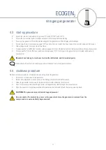
Please ensure this procedure is followed when shutting down the generator.

• 

 Do not turn off the power to the generator

• 

 Isolate all compressed air connections to the Nitrogen Generator and buffer vessel.

• 

 Allow the generator to continue to operate until the display indicates low pressure

• 

 Once low pressure is indicated the generator will depressurise itself through the exhaust valves.

• 

 Once the generator is fully depressurised the power can be switched off and the mains power isolated.

Beware

 it can take up to 

two

 hours to clean the buffer tank, and hit required purity

CAUTION:

 The generator may still retain trapped pressure!

Do not switch off or isolate the power to the generator before the generator is isolated from the 
compressed air source and fully depressurised.

Pease ensure the correct shut down procedure is followed to shut the generator down.

Содержание ECO GEN2

Страница 1: ...User guide ECO GEN 2 nitrogen generator revision 2022 018 document 17 100 0693 2022 Air Gas Solutions LLC www n psi co uk...

Страница 2: ...uccessful business Your business needs to exceed your customers expectations to stand out from your competitors and our service must positively impact your business so you can be successful in doing s...

Страница 3: ...n factors 3 3 product dimensions 7 4 product overview 8 4 1 typical system layout 9 4 2 remote start stop control 10 4 3 start up procedure 11 4 4 shutdown procedure 4 5 control panel displays 12 5 ma...

Страница 4: ...purification solutions inc address 5509 David Cox Road Charlotte NC 28269 USA telephone 1 704 897 2182 internet www n psi com email support n psi com canada nano purification solutions inc address 7 P...

Страница 5: ...uct This user guide is intended solely for such personnel and is to be used only as a reference it should not be used to replace conventional training 2 3 packaging All products are securely packaged...

Страница 6: ...o the generator 3 1 flow rates model rated outlet flow for nitrogen purity outlet maximum oxygen content 99 9 0 1 99 5 0 5 99 1 98 2 97 3 96 4 95 5 Nm3 hr scfh Nm3 hr scfh Nm3 hr scfh Nm3 hr scfh Nm3...

Страница 7: ...nches mm inches mm inches mm inches mm inches ECO GEN2 090 1064 42 440 17 366 14 225 7 110 4 60 2 125 5 ECO GEN2 110 1391 55 440 17 366 14 225 7 110 4 110 2 125 5 ECO GEN2 130 1991 78 440 17 366 14 22...

Страница 8: ...ssure gauge 2 to buffer 1 BSPP or NPT 9 online column pressure gauge 3 from buffer 1 2 BSPP 10 compressed air inlet pressure gauge 4 nitrogen outlet 1 2 BSPP 11 purge flow control 5 mains inlet electr...

Страница 9: ...IMPORTANT It is essential that the system into which the generator is installed is fitted with a pressure limiting relief device This device should be installed between the compressor and the product...

Страница 10: ...contact 5 Green Wire 24V DC Output 6 Yellow Wire 24V DC Output To set up the Remote Start Stop control remove break the connection between the Black wires and green wires connect externally to a remot...

Страница 11: ...ol system will be able to operate fully 4 4 shutdown procedure Please ensure this procedure is followed when shutting down the generator Do not turn off the power to the generator Isolate all compress...

Страница 12: ...he generator has run in Economy mode 3 Start up Sequence During the start up sequence the screen will display Start up will be displayed until the half cycle count has met the de sired set point Colum...

Страница 13: ...nerator clean all surfaces that appear to have attracted unwanted contaminants always check all connections for leakage and secure seating ensure all loose parts are removed or secured to the generato...

Страница 14: ...er of your generator this can be found on the rating plate located top right hand side of the generator Service A Every 1 Year 12 Months Replace External Exhaust Silencers Service B Every 2 Year 24 Mo...

Страница 15: ...lencers 31 100 5011 Replacement Exhaust Silencers x2 Exhaust Silencers 31 100 5013 Replacement Exhaust Silencers x2 Exhaust Silencers 31 100 5150 Replacement Exhaust Valves x2 Exhaust Valves 31 100 51...

Страница 16: ...element failure to cycle Controller not functioning correctly Ensure the controller is powered up check the on screen column status to ensure it is powering the solenoid valves during operation Insuf...

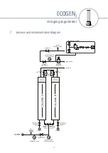
Страница 17: ...REGULTOR FLOW CONTROLLER PURGE VALVES N2 OUTLET VALVE OUTLET PRESSURE SENSOR REGULATED OUTLET PRESSURE GAUGE ONLINE COLUMN PRESSURE GAUGE INLET B SOLENOID VALVE EXHAUST EXHAUST INLET A SOLENOID VALVE...

Страница 18: ...18 nitrogen gas generator ECOGEN2 7 1 wiring diagram Controller Box Earth Pin Enclosure Front Plate Earth Pin O2 Analyser options only Resistor 500...

Страница 19: ...nitrogen gas generator ECOGEN2 notes 19...

Страница 20: ...nitrogen gas generator ECOGEN2 notes 20...

Страница 21: ...nitrogen gas generator ECOGEN2 notes 21...

Страница 22: ...2182 support n psi com www n psi com nano purification solutions st catharines ontario canada tel 1 905 684 6266 support n psi com www n psi com nano purification solutions new bethlehem pennsylvania...

Отзывы: