30
DT Series - Installation manual (V4_2022)
Step 1: Full fire adjustment
Run the burner to its maximum position (high fire). Adjust the burner capacity in
accordance with table 2.
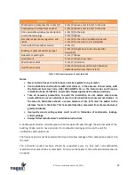
Table 2 data correspond to the values established by the manufacturer during a factory
test and represents those for the required burner capacity.
These data correspond to the desired pressure readings at main gas inlet connection
and at burner, to get the right unit capacity.
Calibration specified in table 2 is obtained by adjusting the gas pressure regulator of the
burner.
Figure 11: Gas pressure regulator
NOTE:
•
Turning the adjustment screw clockwise increases the gas pressure and burner
capacity.
•
Turning the adjustment screw counterclockwise decreases the gas pressure and
burner capacity.
Factory final adjustments
Serial No.
Inlet pressure - burner off
Inlet pressure - high fire
Pressure at burner - high fire
Table 9: Burner section factory test data
Step 2: Combustion readings
Take O
2
and CO readings. Ideally O
2
shall be around 5% at high fire with CO not
exceeding 0.04% (400 ppm).
If required, to increase or decrease O
2
concentration, proceed as follow:

