background image


DT Series - Installation manual (V4_2022)


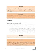
Negligence in maintenance can cause failure of the equipment, property damage and/or harm 
to the building occupants and will void the warranty of the equipment. 

2.4.


RECEPTION & STORAGE 

Immediately upon receipt of the equipment, check the crating and contents for any damage 
that  may  have  occurred  during  the  shipment.  Inspect  protective  covers  for  perforations  or 
other  signs  that  there  may  be  damage.  Remove  protective  covers  and  check  for  external 
damage. Open all the access  doors and check  for internal damage. Close access doors when 
the inspection is finished. Replace covers if the unit is not being assembled or installed at that 
moment.


All  the  units  that  leave  our  factory  are  tested  and  carefully  inspected  immediately  prior  to 
shipping to ensure that they are in good operating condition at that time. Check the packing 
slip  to  make  sure  that  all  loose  parts  for  field  installation  were  received;  they  can  be  found 
inside the unit. If damages are found or parts are missing, please contact your local authorized 
distributor or call factory. 

If  the  equipment  is  to  be  stored  prior  to  installation,  you  must  observe  the  following 
precautions: 


Store in a well-drained and dry area that will not accumulate surface water to prevent 
damage by moisture from wet ground, dew, or rain. 


Do not store where the equipment could be physically damaged. 


Make  sure  that  all  protective  coverings  that  were  provided  for  shipping  are  not 
damaged and are properly installed over the equipment. 


The entire perimeter and any full height cross members of the unit must be supported 
by  a  level  surface  and  the  supporting  surface  must  be  adequate  for  supporting  the 
entire weight of the unit. 


Do not stack split unit sections one over the other for storage purpose. 

2.5.


LIMITED WARRANTY 

Subject to the terms and conditions hereof, during the first year after the original installation 
of  the  product  or  eighteen  (18)  months  from  date  of  shipment  by 

Nagas  Innovation

  Inc. 

whichever  occurs  first,  we  will  supply  free  of  charge  any  component  part(s)  of  our  product 
found  to  be  defective  in  material  or  workmanship  (except  for  the  heat  exchanger  section 
which  carries  a  5-year  warranty).  Any  replacement  part(s)  so  supplied  will  be  warranted  for 
the balance of our product's original warranty. The part(s) to be replaced must be available in 
exchange  for  the  replacement  part(s).  Any  labor,  material,  transportation,  freight  or  other 
charges incurred in connection with the performance of this warranty will be the responsibility 
of  the  owner  at  the  hourly  rates  and  prices  then  in  force.  This  limited  warranty  is  only 
applicable  to  new  and  unused  products  purchased  from  us  or  from  our  authorized 
distributors,  provided  that  our  user  instructions  contained  in  our  user  guide  have  been 

Содержание DT Series

Страница 1: ...ww nagasinnovation com INDIRECT GAS FIRED DUCT FURNACE INSTALLATION OPERATION AND MAINTENANCE MANUAL FOR INDOOR OR OUTDOOR INSTALLATIONS Gas Unit Heaters Gas Packaged Heaters Gas Utility Heaters And G...

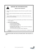
Страница 2: ...uctions o If you cannot reach your gas supplier call the fire department Installation and service must be performed by a qualified installer service agency or the gas supplier THIS INSTRUCTION MANUAL...

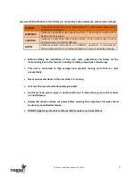
Страница 3: ...r maintenance that are important but not related to personal injury or property damage Before starting the installation of the unit read understand and follow all the instructions given in this manual...

Страница 4: ...______________________________________________________ ADDRESS ___________________________________________________________ PHONE ___________________________________________________________ EMAIL _____...

Страница 5: ...SPECIFICATIONS 12 4 INSTALLATION GUIDELINES 13 4 1 GENERAL 13 4 2 TYPICAL ARRANGEMENT 14 4 3 INSTALLATION 15 4 4 LIFTING 15 4 5 MOUNTING 16 4 6 UNPACKAGING 17 4 7 ELECTRICAL OR CONTROL SERVICE CONNEC...

Страница 6: ...SEQUENCE 34 13 4 TROUBLESHOOTING CHECK LIST 35 14 HEATER MAINTENANCE 37 15 START UP REPORT 38 NOTICE The features illustrations and description in this document were to our knowledge accurate at the t...

Страница 7: ...e is required under the heater Allow sufficient space on both sides of the heater for maintenance and allow sufficient space on the air inlet hood side to prevent snow accumulation and do not block th...

Страница 8: ...n for gas heating units CSA B149 1 ANSI Z223 1 NFPA 54 to the electrical code CSA22 1 NFPA 70 and to local laws rules and regulations All the electrical installation located inside or outside of this...

Страница 9: ...om wet ground dew or rain Do not store where the equipment could be physically damaged Make sure that all protective coverings that were provided for shipping are not damaged and are properly installe...

Страница 10: ...y way for incidental consequential or special damages however caused such as but not limited to loss of productivity damages caused by delays loss of profits and management time In order to obtain rep...

Страница 11: ...r installation in air ducts or in air handling unit made by original equipment manufacturers OEM of listed heating equipment in cabinet It must be mounted on the positive side of the circulating air b...

Страница 12: ...83 18 1 15432 37037 7285 17483 250 3125 911 2500 729 15 1 19290 46296 9106 21854 300 3750 1093 3000 874 15 1 23148 55556 10927 26225 350 4375 1275 3500 1020 18 1 27006 64815 12748 30596 400 5000 1457...

Страница 13: ...will measure the average duct temperature field testing may be required to find the optimal position The installation must be adjusted to obtain a temperature rise within the range specified on the un...

Страница 14: ...e or Twin DWDI blowers with diffuser plate and horizontal arrangement Do not use SWSI blower Single or multiple plenum blower can be used in any configurations For application with high air flow Tempe...

Страница 15: ...he roof or in a horizontal arrangement through the wall or a combination of both The heater should be attached to the roof curb or supporting structure with screws bolts or any other appropriate faste...

Страница 16: ...adequate steel beam Refer to the shop drawing for mounting information 2 Roof curb mounting Roof curbs are fabricated of heavy gauge load bearing galvanized steel and must be fully insulated after ins...

Страница 17: ...built with unit casing and floors designed to prevent water from penetrating the building through the installed equipment All penetrations through the unit walls must be caulked and sealed to prevent...

Страница 18: ...hases power supply check for the correct rotation of all motors and fans If the rotation is incorrect reverse the rotation at the incoming power only All electrical conduit outlets in the control pane...

Страница 19: ...5 to 75 N A 3 4 NPT 85 to 175 N A 3 4 NPT 200 to 350 1 2 NPT 1 NPT 400 to 500 3 4 NPT 1 1 2 NPT Table 4 Vent sizes NOTES 1 Table 3 should not be used to size the gas supply line 2 If gas pressure exce...

Страница 20: ...ulator 6 Automatic safety shut off valve 7 Automatic safety shut off valve 8 Manual ignition cock 9 1 8 NPT diameter test port 10 Piping union 11 Modulating valve OPTIONS 12 Low gas pressure switch re...

Страница 21: ...0 300 350 400 500 500 Table 6 Inlet gas pressure Note Consult factory or rating plate for propane gas inlet and manifold pressures 9 HEATER SHUTDOWN 9 1 EXTENDED SHUTDOWN When the heater is shut down...

Страница 22: ...om 6 to 14 inches The heater is designed to operate effectively and safely against a positive pressure of 0 25 in w c with a positive stack category IV type corrosion resistant single wall or double w...

Страница 23: ...ith the National Fuel Gas Code ANSI Z223 1 NFPA 54 or the Natural Gas and Propane Installation Code CSA B149 1 Local codes always supersede the above provisions Take all necessary precautions to avoid...

Страница 24: ...ere the condensation may accumulate Cover the flue vent on its entire length with thermal liner material to prevent condensation formation while the burner is operating If the room temperature is main...

Страница 25: ...for each unit The installation of two units onto one same exhaust system is forbidden and dangerous A repression of combustion gas of one of the devices could migrate towards the second and cause comb...

Страница 26: ...26 DT Series Installation manual V4_2022 Figure 5 Recommended wall horizontal Flue Vent Exhaust and Combustion Air Duct Concentric kit Figure 6 Recommended wall vertical Flue Vent Exhaust...

Страница 27: ...ny interlock or safety switches under any circumstances Proper commissioning of this equipment is the responsibility of the installing contractor It is recommended that an air balance be completed bef...

Страница 28: ...5 in w c pressure gauge on the test port located at burner inlet downstream of the modulating valve butterfly valve see figure 8 Figure 8 Burner pressure test port location Model C Ensure that all th...

Страница 29: ...detector In that case the UV tube must be placed in the same support used to install the flame rod 11 3 PILOT ADJUSTMENT Turn ON main electrical disconnect and turn control panel selector to BURNER p...

Страница 30: ...specified in table 2 is obtained by adjusting the gas pressure regulator of the burner Figure 11 Gas pressure regulator NOTE Turning the adjustment screw clockwise increases the gas pressure and burne...

Страница 31: ...ow fire adjustment Run burner to LOW FIRE position Take combustion readings and adjust to measure 0 04 CO 400 ppm maximum NOTE It is normal to have high O2 reading Mark the position Make adjustments f...

Страница 32: ...flue gas from the heat exchanger 8 Burner stops and is now ready for a new heat demand Note For general guidance purpose only always refer to the control sequence and wiring diagram provided with the...

Страница 33: ...hem 13 2 STATUS OF WARNING LIGHTS FIREYE The table below lists the most common and important codes concerning unit operation Refer to manufacturer for other codes not listed in this table NOTE A compl...

Страница 34: ...emand and the pilot control valve coil as well as the ignition transformer is energized 3 The FLAME light is ON when the flame safeguard relay detects a pilot flame signal for 10 seconds 4 The MAIN li...

Страница 35: ...valves are opened 5 Check condition of the flame rod ceramic replace if necessary 6 Check the flame safeguard amplifier replace if necessary 7 Refer to the manufacturer Flame failure MTFI CODE 19 FIR...

Страница 36: ...he temperature switch 5 Consult factory Ground fault CODE 54 FIREYE 1 Check grounding of the heater frame and flame safeguard relay 2 Check for ground default in electrical wiring between the heater a...

Страница 37: ...d outlet of the heater Check combustion and flame quality Check that all safety controls are operational Check the operation of the high temperature limit thermostat Ensure that there are no gas leaks...

Страница 38: ...ir openings High limit adjustment Flue vent Top air baffle installed Condensate drain Neutralizer kit Note ____________________________________________________________________ START UP Flame signal __...

Страница 39: ...________________________________________________________________________ ______________________________________________________________________________________ ________________________________________...

Страница 40: ...ies Installation manual V4_2022 1385 Lionel Boulet blvd Varennes QC J3X 1P7 Canada Direct line 1 888 514 8007 Tel 438 338 1101 Fax 450 649 8756 Email service nagasinnovation com Website www nagasinnov...

Отзывы: