background image

18

•  The receiver antennas should be kept away from any metal surfaces whenever 

possible as they can reflect away or shield the incoming RF signal.

•  If the receiver’s volume control is set too high, it may overdrive the input of the 

attached audio mixer, causing distortion. Conversely, if the output is set too low, the 

overall signal-to-noise ratio of the system may be reduced, causing noticeable hiss. 

If such noise occurs, adjust the output level of the receiver so that highest sound 

pressure level going into the microphone transmitter causes no input overload in 

the mixer, but permits the mixer level control to operate in the normal range (not 

too high and not too low). This provides the optimal signal-to-noise for the entire 

system.

•  Before inserting the batteries, ensure that they are inserted with the correct polarity.

•  Before operation, confirm that the receiver and associated transmitter are tuned to 

the same frequency group and channel number.

•  After making a receiver channel change, ensure that the corresponding change is 

also made on the matching transmitter.

•  Use only new alkaline or fully recharged NiMH batteries. Do not use “general 

purpose” carbon batteries. When batteries are weak, replace all the batteries at the 

same time. Do not mix new and old batteries.

•  Position the receiver so that it has the least possible obstructions between it and the 

transmitter. Line-of-sight is best!

•  During operation, the transmitter and the receiver should be as close as possible for 

optimum results but never closer than 3 ft. (1 m) as that may overload the receiver’s 

input circuitry and cause noises.

•  If rack mounting the receiver, keep away from heat sources such as amps by 

allowing enough space between them for adequate ventilation.

•  For the best operation, the receiver should be placed at least 3 ft. (1 m) above the 

ground and 3 ft. (1 m) away from a wall or metal surface. The transmitter should 

also be at least 3 ft. (1 m) from the receiver. keep antennas away from noise 

sources such as motors, automobiles, neon lights, signal processors, computers, as 

well as large metal objects.

• A receiver cannot receive signals from two or more transmitters simultaneously.

•  Turn the transmitter off when it is not in use. For longest life, remove the batteries if 

the unit is not to be used for a long period as the transmitters draw a tiny residual 

current to maintain the programmed settings, even when turned off. Also, since 

batteries installed for a long time can sometimes corrode and/or leak, causing 

damage, it is generally recommended that batteries be removed whenever the 

transmitters are not being used.

•  When using the bodypack for instrument use: Scratchy noises can sometimes occur 

when an electric guitar with dirty pots or connections is used with a wireless system. 

Therefore, the supplied capacitor provides first-order filtering of the RF signal from 

the cord into the guitar and eliminates virtually all scratchy noises. Should your 

equipment still produce scratchy noise, we suggest these steps to eliminate problems:


 1)  Make sure all guitar volume and tone pots are clean and all contacts are 

solid. This is very important.


 2)  Solder a 47pF capacitor across the pot to ground terminal of the guitar’s 

volume and tone pots to provide extra filtering.

8. MISCELLANEOUS TIpS

Содержание U-800

Страница 1: ...U 800 UHF 800 Channel Wireless System OWNER S MANUAL ...

Страница 2: ...accessories 22 13 Service Information 22 14 One Year Limited Warranty 23 Thank you for choosing the Nady U 800 wireless system and congratulations on your choice The U 800 has the best performance and price value in professional UHF wireless offering clear channel frequency agile operation on the UHF band for interference free performance in any application or locale The U 800 delivers 800 user se...

Страница 3: ... Half rack receiver design with unique snap out side panel locking tabs for single receiver or dual receivers side by side optional rack mounting Externally powered with included DC adapter 120VAC 22VDC 400 mA Choice of transmitters UH 800 handheld Mic or UB 800 bodypack lavalier LT Headmic HM or instrument GT UH 800 Handheld Mic Transmitter Sleek metal housing with internal antenna for optimum ae...

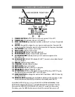
Страница 4: ...group number 12 CHANNEL indicates channel number 13 MUTE LEVEL shows muting level 14 SCAN ICON indicates scanning is in progress 15 FREQUENCY indicates frequency in MHz 16 UP BUTTON BUTTON to change the receiver MUTE level up GRP CH up by one step at a time or activate ASC sync in IR menu 17 DOWN BUTTON to change the receiver MUTE level down GRP CH down by one step at a time 18 MENU BUTTON repeate...

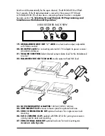
Страница 5: ...ternal AC DC adapter to power receiver DC22VDC 400mA 21 VOLUME CONTROL Selects desired output volume level for the Unbalanced Line Out 22 BALANCED MIC OUT XLR JACK Audio output at fixed MIC level 23 DC POWER SUPPLY ADAPTER 120VAC 22VDC 400mA 24 SIDE MOUNT CLIP removes to leave space for optional rack ears 25 ERM 12 SINGLE RACK KIT optional rack ears for single receiver rack mounting 26 EJC 3 JOINI...

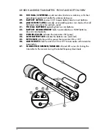
Страница 6: ... TWO AA BATTERIES operating from two AA batteries 32 BATTERY COMPARTMENT holds two AA alkaline or NiMH batteries observe correct polarity 33 POWER ON LED indicates the transmitter ON green 34 LOW BATTERY LED indicates the batteries are weak red 35 RF POWER slide the switch to power the transmitter ON or OFF 36 AUDIO MUTE slide the switch to ON or OFF to mute audio with transmitter powered on 37 IR...

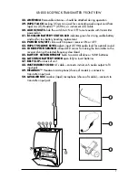
Страница 7: ... power receiver ON or OFF 43 INPUT VOLUME LEVEL adjusts input LT HM audio level for optimal sound 44 IR RECEPTOR SENSOR infrared LED sensor for linking the transmitter to the receiver during IR selected frequency download 45 BATTERY COMPARTMENT holds two AAA alkaline or NiMH batteries 46 LATCHING BATTERY DOOR open fully to insert batteries 47 BELT CLIP on back of unit 48 INSTRUMENT CORD GT cable c...

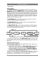
Страница 8: ...is pressed one step at a time for Auto Scan Frequency or to Automatic GR CH ASC Sync or if pressed repeatedly the LCD DISPLAY 5 menu will cycle through the following screens v During manual programming press the MENU BUTTON 18 to confirm the selec tion and advance to the next menu before the Auto Programming Function takes over after 5 sec Rack Mounting the Receiver There are 2 options available f...

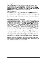
Страница 9: ...hould be adjusted to a lower number for the minimum RF squelch setting at which the RF INDICATOR 8 will remain on while your transmitter is in normal use up to the maximum operating range antici pated in use for your application However in areas of high RF activity the squelch control may need to be adjusted to a higher number If the transmitter is off and the receiver s signal RF INDICATOR 8 or t...

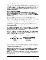
Страница 10: ... Line Out directly to your instrument amp or preamp At maximum receiver volume setting the system output is approximately 4dB higher than a direct cord to amp connection For balanced Output connection plug an audio cable with an XLR connector into the Balanced Mic Out XLR Jack socket and plug the other end into your mixing board or amplifier and control the audio levels from there Both the Unbalan...

Страница 11: ... The BATTERY LED 34 will stay off indicating usable battery strength In the case of a dead or low battery the low battery LED will light red continuously indicating that the batteries should be replaced with fresh ones To preserve battery life turn the transmitter off when not in use To turn the transmitter off slide the RF POWER 35 switch to the OFF position The POWER ON LED 33 is not lit up indi...

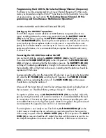
Страница 12: ... and speaker placement Programming the UB 800 to the Selected Group Channel frequency The transmitter must be programmed to the same frequency as selected for the re ceiver via automatic synchronization using the IR ASC Sync function It can not be programmed on the transmitter itself See in next section 6 Selecting Group Channel IR Programming and Simultaneous Multichannel Opera tion UB 800 Bodypa...

Страница 13: ...of the above U 800 receiver instructions Note The transmitter has a removable ANTENNA 38 For best operating range it should be attached screwed on tightly counterclockwise or exchange with another type For best transmitting power during use make sure it is not blocked For optimum range maintain line of sight no obstructions between the transmitter and the receiver whenever possible A walk test bef...

Страница 14: ...nnot be pro grammed on the transmitter itself See next section 6 Selecting Group Channel IR Programming and Simultaneous Multichannel Operation Note Note The transmitter should be turned ON and ready for the IR communica tions with the receiver IR receptor for the following process Note If no button is pressed within the five seconds period during a selection the program is terminated and the proc...

Страница 15: ...AY 5 shows the scanning process which normally takes about two seconds When it finds an interference free channel the receiver stores the channel for use and it will begin ASC sync IR download of the selected channel to the transmitter automatically To manually scan the selected Group Channel press the MENU BUTTON 18 twice for AUTOSCAN menu press UP BUTTON 16 once and it will start scanning A runn...

Страница 16: ... location for simultaneous multichannel operation If you are using multiple transmitters at the same location set up the first transmitter and leave it ON and keep 10 feet away from the receivers and 1 foot away from transmitter to transmitter This avoids possible duplicate selection of the same channel as already selected for the first receiver Then start the autoscan function on the second recei...

Страница 17: ...o not need a license to operate this wireless microphone system Nevertheless operating this microphone system without a license is subject to certain restrictions the system may not cause harmful interference it must operate at a low power level not in excess of 50mW and it has no protection from interference received from any other device Purchasers should also be aware that the FCC is currently ...

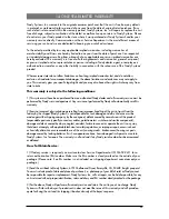
Страница 18: ... that may overload the receiver s input circuitry and cause noises If rack mounting the receiver keep away from heat sources such as amps by allowing enough space between them for adequate ventilation For the best operation the receiver should be placed at least 3 ft 1 m above the ground and 3 ft 1 m away from a wall or metal surface The transmitter should also be at least 3 ft 1 m from the receiv...

Страница 19: ...LUME line level pot MENU UP DOWN buttons LCD Display MUTE AF RF bars A B diversity IR GR CH MUTE Level SCAN Frequency LED indicator Power on Audio Outputs LINE OUT UNBALANCED adjustable line audio output MIC OUT BALANCED Fixed Mic level audio output Output Impedance Unbalanced 1k Ω and Balanced for 600 Ω loads Power Requirement 22VDC 0 4A Antennas Dual permanently attached swivel antennas Dimensio...

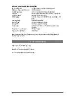
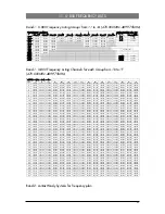
Страница 20: ...r Power ON GREEN and Low Battery ON RED Antenna Type External Removable Battery Type 2 x AAA alkaline or NiMH Battery Life 6 8 Hours typical alkaline Dimensions 3 25 W x 2 18 D x 1 H 8 25cm x 5 53cm x 2 54cm Weight w o batteries 3 9 oz 111g Housing Construction ABS Plastic Specifications subject to change at any time without prior notice for purposes of product improvement 10 Frequency Plan 800 Ch...

Страница 21: ...250 475 500 476 750 478 000 479 250 480 500 481 750 483 000 484 250 485 500 486 750 488 000 489 250 22 470 525 471 775 473 025 474 275 475 525 476 775 478 025 479 275 480 525 481 775 483 025 484 275 485 525 486 775 488 025 489 275 23 470 550 471 800 473 050 474 300 475 550 476 800 478 050 479 300 480 550 481 800 483 050 484 300 485 550 486 800 488 050 489 300 24 470 575 471 825 473 075 474 325 475...

Страница 22: ...of the package that you are returning If your unit is out of warranty please enclose a cashier s check or money order or pay by credit card per instructions by the Nady Service Department Ship your unit prepaid to Nady Systems Service Dept 6701 Shellmound Street Emeryville CA 94608 Include a brief description of the problem you are experiencing For service of a unit under warranty please follow th...

Страница 23: ...artment Any service not performed by Nady will automatically void this warranty 2 Items not covered physical damage resulting from improper handling of the unit in transit from the factory by the shipper Nady Systems is not responsible for such damage and all such claims must be made against the shipping company by the consignee defects caused by normal wear of the product expendable parts are typ...

Страница 24: ...nada Operation is subject to the following two conditions 1 this device may not cause harmful interference and 2 this device must accept any interference received including interference that may cause undesired operation NADY SYSTEMS INC 6701 Shellmound Street Emeryville CA 94608 USA Tel 510 652 2411 Fax 510 652 5075 www nady com ...

Отзывы: