background image

Mydax, Inc. 

1M150W 

Water Cooled Chiller 


Designed for Lockheed Martin   

11 


 DIAGNOSTIC 

DISPLAYS


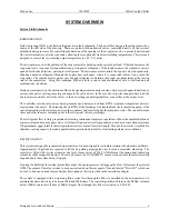
Mydax chillers are provided with a computerized self-diagnostic capability.  This system is equipped with 9 different test 
panels, which are accessed by pressing the TEST key, followed by the test panel number.  Diagnostic mode is terminated 
by pressing the CLEAR key, and results in a display similar to that below: 
 

MAIN DISPLAY:


Diagnostic messages are displayed on the main 2 by 40-character LCD.  Display 5 automatically appears when the TEST 
key is first depressed.  Once in diagnostic mode, other displays can be selected by depressing number keys 1 through 9.  
The following describes each of the test displays: 


TEST PANEL #1:


Numbers represent the drive signals for the evaporator, bypass and superheat valves and tank heaters.  Heater 
values are inactive in this system.  The range is 0 (minimum) to 20 (maximum drive).  Each digit represents 5% 
of the available 24V drive voltage.   Avg Valve shows a 32 second running average of the valve's drive, 
displayed above it. 


TEST PANEL #2:


This display shows the refrigerant circuit RTD temperatures in 

°

C.  The display reads: 


Limit   = Max Evaporator Temp 

Suct    =   Suction Temp   

Psia    = Suction Pressure (absolute) 

Sup.Ht = Superheat Temp    

SHavg = Avg Super Ht Temp 

Cond  = Condenser Temp 


The condenser reading is a direct indicator of condenser temperature and pressure.  The microprocessor sends 
the CONDENSER HOT error message if the condenser temperature e54

°

C. 


TEST PANEL #3:


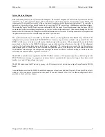
The first 3 sets of 4-digit numbers are hexadecimal.  They represent correction values for the slow gain servos 
for up to 3 reservoirs.  The function of this servo is to dynamically adjust the main temperature control servo to 
near zero error and thereby maintain temperature stability. 


The first 2 digits in each set of 4 show the gain offset.  Each increment equals 0.05

°

C, so 14 Hex = 20 decimal 

= 1.0

°

C.  This value is internally subtracted from the operator-entered temperature set point if the actual 

temperature is above the set point, thus reducing the coolant temperature.  The set point offset is continuously 
monitored by the controller and adjusted according to current conditions. 


The second 2 digits in each set of 4 show the time prescaler.  This is a counter which increments or decrements 
once a second and times the next update of the set point offset.  A typical value is 20 seconds per offset change. 
 When the count reaches "00", the offset may or may not be changed and the count resets to "0A" Hex (10 
decimal).  Together these numbers show that the controller is internally changing the control set point to 

 Tank        --- MYDAX ---     Local Set 

 24.95°C   35.8 Gpm     400K

    25.0°C


 Valve         5         11  18  Htr   0 
Avg Valve      0          6  15  Htr   0


-5.0

°


 -11.4

°

  25.5   13.5

°

   8.0

°

   38.4

°


Limit  Suct   Psia  Sup.Ht  SHavg. Condr


302B  0000  0000  Z 0.00  G  51.95   8.0 
SS-1  SS-2  SS-3 RTD Reference    SH Avg


Содержание 1M150W

Страница 1: ...vanced temperature control technology MYDAX INC INSTRUCTION OPERATION MANUAL 1M150W WATER COOLED CHILLER MYDAX INC 12260 Shale Ridge Road Auburn CA 95602 530 888 6662 FAX 530 888 0962 http www mydax c...

Страница 2: ...YSTEM OVERVIEW 4 INSTALLATION 6 FRONT PANEL CONTROLS 8 ALARM ERROR MESSAGES 10 DIAGNOSTIC DISPLAYS 11 SERVICE WARRANTY 14 SHIPPING STORAGE PROCEDURE 15 DRAWINGS PARTS LIST FRAME DRAWING FLUID DIAGRAM...

Страница 3: ...70 F 7 Gpm 40 F 20 PSI differential Electrical Service 460 480 VAC 60 Hz 3 phase 50 amp service Physical Parameters 65 H x 36 W x 58 D 1000 lbs dry weight STANDARD FEATURES This chiller is complete wi...

Страница 4: ...reas where potentially harmful conditions exist and in this manual to bring attention to such conditions This chiller uses materials that are subject to environmental regulations be sure to familiariz...

Страница 5: ...mpressor is hermetically sealed and no service should be required In the event that cleanup is necessary absorb oil with oil absorbent material and dispose of as a hazardous waste Follow approved clea...

Страница 6: ...TD s resistance temperature devices located about the circuit The drawing shows RTD s at the discharge line leading from the recirculating pump at the return line leading to the reservoir between the...

Страница 7: ...one power relay coil and a relay pole RL1 B The RESET switch serves to feed power to the relay which energizes the contactor When energized the contactor feeds power back to the relay so the RESET swi...

Страница 8: ...e starting to allow the crankcase heater to separate the refrigerant from the oil CONDENSER FLOW The condenser inlet and outlet fittings are 1 stainless steel female pipe thread fittings FPT Plumb the...

Страница 9: ...ow rate is visible on the front LCD display panel BYPASS VALVE To divert the recirculation flow from the output path back to the tank first open the Bypass valve then close the output flow adjustment...

Страница 10: ...ition is eliminated or the MUTE ALARM switch is depressed again Pressing MUTE ALARM when no alarm is active causes the alarm to sound once and the TEST ALARM display to appear SET Enables SET TEMPERAT...

Страница 11: ...decrements toggles tank temperature setpoint temperature and evaporator data view modes for multiple channel systems DECIMAL Display shows model number and software revision date and copyright RUN PU...

Страница 12: ...s too close to freezing 4 C The microprocessor shuts down the system with a fatal alarm Push Reset Indicates that a fatal alarm in the interlock circuit has occurred and the operator must push the Res...

Страница 13: ...a direct indicator of condenser temperature and pressure The microprocessor sends the CONDENSER HOT error message if the condenser temperature exceeds 54 C TEST PANEL 3 The first 3 sets of 4 digit nu...

Страница 14: ...e the Flow OK relay below the selected GPM The output of the relay is wired to a BNC connector labeled Flow OK located on the rear panel of the unit The shield and center pin are the normally open con...

Страница 15: ...setpoint temperatures of whichever recirculating channel was last selected at the Main Display and the system wide alarm history The second line indicates which recirculating channel was last selecte...

Страница 16: ...use of a torch In particular service of Mydax refrigeration circuits requires attention to the following 1 Use caution to protect components from heat damage 2 Prevent any moisture from entering the...

Страница 17: ...en run with water ethylene glycol should be added to the recirculating loop Verify that the concentration of ethylene glycol approaches 50 measure with a hydrometer in the recirculating loop before dr...

Отзывы: