Temposonics
®
R-Series
V
EtherNet/IP™
Operation Manual
I 23 I
NOTICE
Physically connect the sensor to your network, but do not apply
power to the sensor. You will be instructed when it is time to power
the sensor.
6.
Programming and configuration
6.1
IP address Configuration
An example of configuring an MTS EtherNet/IP™ sensor will be
shown using an Allen-Bradley CompactLogix L35E controller, and
the RSLogix 5000 software from Rockwell. This example is written
with the understanding that the customer already has an EtherNet/
IP™ capable controller, and a working EtherNet/IP™ network.
The procedure to incorporate an MTS EtherNet/IP™ sensor into a
network is shown in the following 3 steps. Step 1 describes setting
the IP address of the sensor and step 2 installing the MTS EtherNet/
IP™ EDS file (download at www.mtssensors.com). To utilize the
EDS file with the add-on profile feature, the RSLogix 5000 software
must be version 20 or later. By using the EDS add-on profile, the
sensor parameters and configuration data are loaded automatically
to complete steps 3.1 and 3.2. If not installing the sensor EDS file,
or if using an earlier version of the RSLogix 5000 software, chapters
7.3 through 7.5 describe how to manually load the sensor parameter
data. Also, if needed later, the descriptions in step 3.2 can help when
reviewing the sensor parameter data and for making any changes.
NOTICE
1.
Choose an IP address that is not being used on your network or
subnetwork.
2.
After the IP address is assigned to the sensor, record the IP
address and have it available as you will need it to communicate
with the sensor.
6.2 Setting the IP address of the sensor
Each sensor comes from the factory with DHCP mode active, and a
unique MAC ID (see sensor label). This allows you to communicate
with the sensor in order to configure the sensor for your network.
Before you can use a sensor on your network you must first assign
it an static, unused IP address on your network. In the following
example we will use Rockwell’s BOOTP/DHCP Server program to
assign an IP address to the sensor.
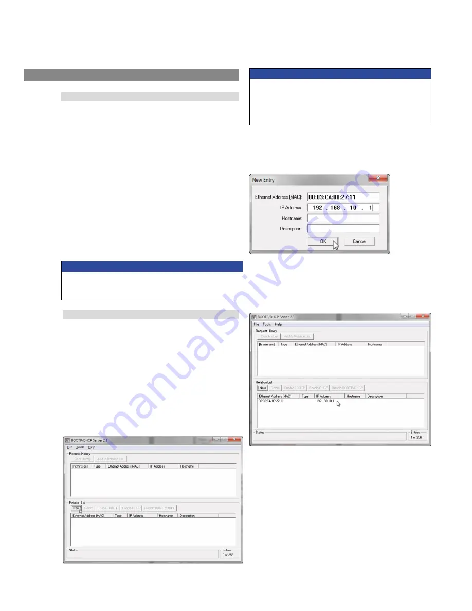
6.2.1
Open the
BOOTP/DHCP Server
software.
The ‘BOOTP/DHCP Server’ window opens.
6.2.2
To add your sensor to the ‘Relation List’, click the
New
button
in the ‘Relation List’ pane.
The ‘New Entry’ window opens.
Fig. 26: Create new relation list entry
Fig. 27: Enter MAC ID and unique IP address
Fig. 28: Populated relation list
6.2.3
In the ‘New Entry’ window, enter the
MAC ID
(see sensor label).
Enter a unique
IP address
you will use for the sensor,
record
the IP address
and click
OK
.
6.2.4
Verify that your unique IP address and MAC ID appear in the
‘Relation List’ window. If the relation list window does not
contain both MAC ID and IP address, repeat steps 6.2.2 to 6.2.4.
Otherwise, continue to step 6.2.5.


