


Page 504
3. If the maximum offset exceeds .the
Parallel dimension .015 inches, loos-
en the motor or pump and place thin
metal shims under the motor or pump
feet until the offset is set properly.
4. Torque down the motor or pump.
5. Recheck alignment.
The angular alignment dimension needs
to be 0.070 or less.
1. Using a micrometer or caliper, measure
from the outside of one flange to the
outside of the other at intervals around
the periphery of the coupling. DO NOT
rotate the coupling
2. Determine the maximum (B) and
minimum (C) dimensions. Refer to
Figure 2-4.
Figure 2-1
Figure 2-2
3. Support the baseplates on metal
shims or wedges having a small
taper. (Refer to Figure 2-2)
a. Place shims close to the founda-
tion bolts. (Refer to Figure 2-2)
Figure 2-3
A
4. Torque down the motor or pump.
5. Recheck the parallel alignment
above.
If the parallel (.015 inches) or angular
(.070 inches) misalignment is great, this
is an indication of baseplate distortion
and must be corrected first, refer to 2C
Leveling.
After all leveling and alignment opera-
tions have been completed, piping can
begin. After the piping has been com-
pleted, refer to 2E1 Piping Alignment.
Alignment of the unit must be checked
again to make certain that no piping
strains are causing distortion. After
approximately two weeks of operation,
check the alignment again to make
sure that temperature changes, piping
strain, or foundation variations have not
caused misalignment. If alignment has
been maintained over this period, the
pump and motor can be doweled to the
baseplate.
2E Piping
2E1 Piping Alignment
It is important that all piping be lined up
and not forced into place. It is recom-
mended that you begin piping at the
pump. If the lines are ended at the
pump, particularly if the last piece is cut
a little too short or long, the pump will
be forced to meet the pipe and strain or
distortion will result.
2E2 Piping Support
Never allow the pump to support piping.
Other means such as pipe hangers
and pipe supports should be used to
carry piping to avoid misalignment and
distortion. Consideration should be
given to thermally induced expansion
and contraction, particularly in long runs
of straight pipe.
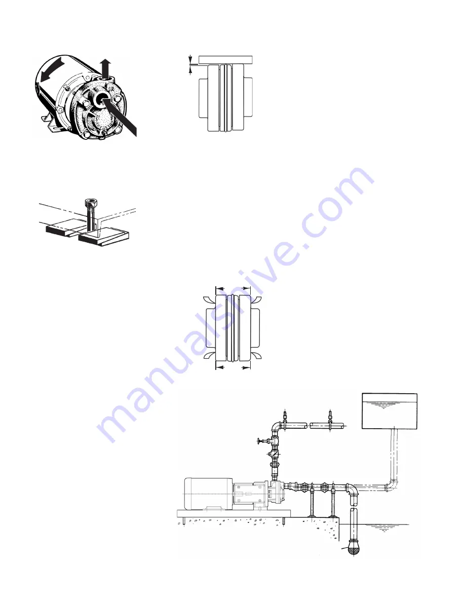
Fasten Unit Securely to Foundation
Level Position
Gate Valve
Check Valve
Eccentric
Reducer
Increaser
Vent Plug /Drain
Pipe
Supports
Union
Union and Spool
Piece
Combination
Foot Valve and
Strainer
Area of Foot Valve 1 1/2
Times Pipe Area
Area of strainer 3 to 4
Times Pipe Area
Pipe Hangers
Suction Reservior
Long Suction Lines to have Continual Rise
From Source. Eliminate High Spots
Elbow 10 to 20 Pipe
Diameters from Pump
Suction
Arrangement of Suction Piping for
Head-on Suction
Figure 2-5
Figure 2-4
B
C
Outlet
Rotation
Inlet
b. Place shims close to where the
greatest weight is located.
4. Check the baseplate for distortion:
a. Place a straightedge along the
baseplate to determine if it is dis-
torted.
b. Adjust the shims until the
baseplate is not distorted.
5. Use a section of the pipe to de-
termine if the inlet and discharge
openings are vertical and located
properly.
6. Correct the positions, if necessary, by
adjusting the shims.
2D Alignment
Although flexible coupled pumps are
carefully aligned prior to crating and
shipping, it is almost a certainty that
strains imposed during transit have
altered the alignment. Complete the
following steps after the unit has been
placed on the foundation and leveled.
The standard coupling supplied by
MTH Pumps has an elastomer member
between two internal serrated flanges.
They have smooth outsides of equal
diameter. These surfaces are used for
alignment procedures.
To check the PARALLEL alignment:
(Refer to Figure 2-3)
1. Place a straightedge across the two
coupling flanges.
2. Measure the maximum offset (A),
Figure 2-3, at various points around
the periphery of the coupling. DO
NOT rotate the coupling.
3. If the difference between the
maximum and minimum exceeds the
Angular dimension (0.070 inches),
loosen the motor or pump and place
thin metal shims under the motor or
pump feet until the angular alignment
is correct.


