Operation
FLEXIBLE COUPLED PUMPS
CLOSE COUPLED PUMPS
A.
Rotation
B.
Inlet and Outlet Locations
C.
Foreign Material
D.
Electrical
E.
Adjustments
F.
Cooling Water
G.
Priming
H.
Starting
I.
Stopping
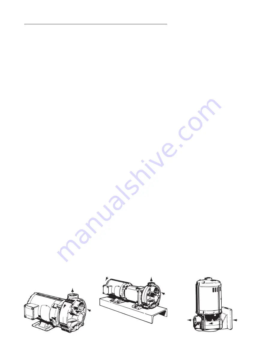
3A Rotation
The standard direction of rotation for
the pump is right handed, or clock-
wise, when looking at the motor end
of the pump. A rotation arrow, refer
to Figure 3-1, is located on the pump
to indicate the correct direction of
rotation.
Operating the pump in reverse will
cause substantial performance varia-
tions and can damage the pump.
Always confirm correct motor rotation
prior to connection of the coupling.
If this is not possible, perform a final
rotation check as follows:
1. Jog the motor briefly.
2. Observe rotation as the unit
comes to a stop.
3. Rotation should be in the direction
of the arrow.
If the motor operates in the wrong
direction:
1. Interchange any two leads on a
three phase motor.
2. On a single phase motor, change
the leads as indicated on the con-
nection box cover. Some single
phase motors may not be revers-
ible.
Figure 3-1
3B Inlet and Outlet Locations
(Refer to Figure 3-1)
The pump inlet is located on the
end farthest from the motor. The
discharge or “outlet” can be on the
top, side, or bottom depending on the
model and construction of the pump.
Normal discharge position is on top.
3C Foreign Material
All regenerative turbine pumps have
close running clearances in order
to maintain efficiency. Take extra
precautions to insure that no foreign
material larger than 25 microns
or .001 inches is allowed to pass
through the pump. Even particles
of this size will damage the pump
if allowed to circulate continuously.
Regenerative turbine pumps are not
designed for slurries.
Large particles, weld spatter, and
other material found in new piping
systems will bend the impeller vanes
and can sometimes lock up the
pump. If a new pump does not oper-
ate properly, the first thing to check
for is damage from foreign material.
3D Electrical
It is important to be aware of and fol-
low the appropriate local and national
electrical codes. Do not make wiring
alterations that can affect motor
rotation without reconfirming correct
rotation. Select starter heaters and
wiring for the maximum current the
motor can use at full service factor
loads.
When making electrical connec-
tions to motors provided with threaded
stud electrical terminals, the recom-
mended torque should be 13-16 inch-lbs.
Applying torque in excess of this range
3.
Section
T51 • E51
Page 506
Dated
February 2014
may cause damage.
Regenerative
turbine pumps will typically use extra
power for a period until they run in.
This can take three to four weeks
depending on the duty cycle. During
this period, impellers are finding their
hydraulically balanced position.
3E Adjustments
No adjustments are required or
advisable on new pumps, other
than those required for installation.
Because of the tight tolerances of
regenerative turbine pumps, it is
not uncommon for the pump to be
difficult to turn over by hand after the
internal parts have been allowed to
dry out . New pumps from the factory
are tested using rust inhibiters to
help preclude this possibility. On site
system flushing may remove these
inhibitors and subject the pump to the
risk of lock up, if it is allowed to dry
out. In this case, do the following:
1. Fill the pump with fluid (wait 2
hours).
2. Insert 5/32” Allen wrench into
lock collar setscrew and rotate
shaft, using the Allen wrench as
a handle. (DO NOT LOOSEN
SETSCREW)
3. Remove the Allen wrench.
4. Jog the pump momentarily using
the on/off buttons if so equipped.
5. This should “break” the impeller
loose without damage, unless
foreign material has entered the
pump.
This procedure will flush residue from
the close fitting impeller surfaces. If
not immediately successful, refer
Inlet
Rotation
Outlet
Rotation
Inlet
Outlet
Outlet
Inlet
Rotation
T51 • E51 SERIES


