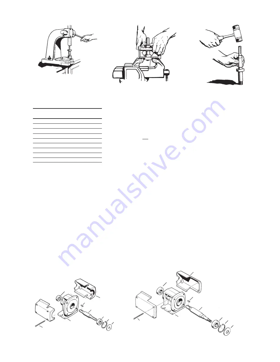
Figure 4-24
Section
T51 • E51
Page 517
Dated
February 2014
P3 & P15 BEARING PEDESTAL
Figure 4-19
P3 Bearing Pedestal
Figure 4-20
P15 Bearing Pedestal
30
23
17
24
4
21
3
33
24A
30
23
17
24
4
33
24A
3
21
Figure 4-23
Figure 4-25
must seat against the shoulder for
proper alignment. Refer to Figure
4-23. *Also refer to Alternate
bearing installation procedures.
CHART 1
NAME/DESCRIPTION
PART
NO.
QTY.
Bearing Pedestal
3
1
Snap Ring/Bearing Retainer
4
1
Shaft
17
1
Flinger
21
1
Key Coupling
23
1
Ball Bearing/Inboard
24
1
Ball Bearing/Outboard
24A
1
Coupling Guard/Halves
30
2
Capscrew
33
4
2. Place the pedestal, pump mount-
ing surface up, in a vise or suitable
fixture and insert the bearing
assembly. It should be possible to
install the shaft assembly with firm
thumb pressure. Refer to Figure
4-24. If more force is required, the
butt end of a hammer handle or
plastic mallet may be helpful. The
shaft assembly should never be
forced or driven in.
3. Install the snap ring (#4) in the
pump end of the pedestal. Be
sure the snap ring is seated prop-
erly in the groove. The beveled
edge of the ring should face away
from the bearing.
4. Install the flinger over the snap
ring. The bearing pedestal is now
ready for pump and motor instal-
lation.
*Alternate bearing installation
procedures.
If an arbor press is not available,
the bearings may be installed on the
shaft using the following procedure:
This procedure is not recommended
and should only be used in an emer-
gency situation.
1. Stand a piece of 3/4” pipe for P3
or a 1-1/4” piece of pipe for P15,
with the threads cut off, on a work-
bench or similar flat surface, with
the bearing placed on the correct
shaft end.
2. Insert the shaft into the pipe so the
bearing is between the pipe and
the shoulder of the shaft. Refer to
Figure 4-25.
3. Using extreme caution, gently tap
on the end of the shaft until the
bearing rests against the shoulder.
Never attempt to install the bear-
ings by striking the outer race.
4. Repeat step 3 for the other bear-
ing.
4E Testing and Final Adjustments
1. Check to be sure that the rotating
assembly turns freely. Turn the
shaft by hand. If it is tight or rough
spots are encountered, it is likely
that at least one of the bearings
was damaged during disassembly/
assembly operations and will have
to be replaced.
2. Look to make sure that the lip
seals on the bearings are posi-
tioned properly in their grooves.
Correct if necessary. As the
bearings are turned, the grooves
should appear wet with oil but
have no visible grease present.
3. Recheck the snap ring on the
large bearing end. It should be
firmly in place, and no axial motion
should result from gentle tapping
on either end of the shaft. (Use a
soft mallet so shaft surfaces are
not damaged.)
4. No adjustments are possible or
required. Proceed with the ap-
propriate pump end assembly
operations. Refer to Section 4
SERVICE - PUMP ENDS (Final
testing is done after the pump end
is in place.)


