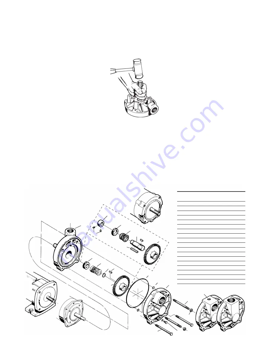
Figure 4-4
Section
T51 • E51
Page 510
Dated
February 2014
Figure 4-10
1
14
15
125
23A
11
8
18
20
T51 C3
17
12
23
7
2
19
C3 - D31 - P3 CLOSE
COUPLED PUMP
P3
d. Slide the motor bracket straight
off. Do not attempt to remove
the motor bracket without first
removing the “O” rings (#8).
8. Remove the seat portion of the
seal. Refer to Figure 4-10.
that a new replacement seat
be installed during reassem-
bly.
4D Disassembly D3 (E51)
The following tools and equipment
are needed for disassembly of E51
Series Pumps:
1. Soft plastic or wooden mallet.
2. Small ball peen hammer.
3. 9/16” wrench or socket
4. Snap ring pliers.
5. Penetrating oil.
6. 1” wood dowel (Approx. 6” long.)
7. Thin blade screwdriver.
8. Cealube G or similar glycol base
lubricant. (DO NOT use petroleum
products.)
To disassemble the pump:
Refer to Figure 4-4 for reference to
the numbered parts in the procedures
below.
1. Remove all liquid from the pump.
2. Remove the four (4) 3/8” X 4” bolts
(#19) from the cover. (#2)
cedure usually does not require
excessive force. Care should
be taken not to damage the hub
or motor shaft.
6. Remove the rotating element
from the shaft. The element
normally adheres tightly to the
motor shaft and some force may
be necessary to remove it. This
is common and if care is taken,
the element can be reassembled
and reused.
It is recommended
that a new rotating element be
used for reassembly.
DO NOT
attempt to remove the seal using a
screwdriver or other sharp object.
Damage to the shaft or element
can occur.
7. Before the motor bracket (#1) can
be removed, the four (4) “O”rings
(#8), located on the upper left and
right studs must be removed.
a. Gently tap on the back of the
motor bracket, alternating
between the left and right side,
until the motor bracket moves
approximately 1/4”.
b. Tap the motor bracket face to
move it back to its original posi-
tion.
c. Remove the “O” rings by sliding
them off the studs.
a. Place the motor bracket face
down on a flat surface.
b. Look into the opening in the
center of the bracket, you will
see a portion of the seat.
c. Insert the 1” dowel, and very
gently, tap the seat until it drops
out. Care must be taken with
the seats. They are often a
brittle material and are prone to
breakage.
It is recommended
NAME/DESCRIPTION
PART
NO.
QTY.
Motor Bracket
1
1
Cover
2
1
“O” Ring/Casing
7
1
“O” Ring/Guide Rod
8
4
Impeller
11
1
Snap Ring
4
1
Seal Rotating Element
12
1
Seal Stationary Seat
125
1
Lock Collar/Sleeve
14
1
Setscrew/Lock Collar
15
2
Shaft Sleeve
17
1
Guide Rod (Qty. 4 on Stainless Steel)
18
2
ThruBolt (Qty. 0 on Stainless Steel)
19
2
Nut (Qty. 4 on Stainless Steel)
20
2
Pipe Plug/Drain
22
1
Optional Vent/Port Plug*
22A
1
Key/Impeller Drive
23
1
Key/Sleeve Drive
23A
1
125
12
4
11
T51
E51
E51 D3
22
Optional Cover Configurations
22A Not Shown
*Serial Number Specific
Contact factory for size


