background image

Preface  

MS-S0081   

x

Preface  

MS-S0081   

Contents

Copyrght Notce ............................................................................................ 
Trademarks ................................................................................................... 
Revson Hstory ............................................................................................ 
Techncal Support .......................................................................................... 
Safety Instructons .........................................................................................
Chemcal Substances Informaton ............................................................... v
Battery Informaton ....................................................................................... v
CE Conformty ............................................................................................... v
FCC-B Rado Frequency Interference Statement ......................................... v
WEEE Statement ......................................................................................... v

1

   Overview1-1

Mainboard Specifications

 ...........................................................................1-2

Manboard Layout ......................................................................................1-4

2   Hardware Setup 2-1

Quck Component Gude ............................................................................2-2
CPU (Central Processng Unt) ..................................................................2-3
Memory ......................................................................................................2-6
Storage .....................................................................................................2-10
Power Supply ...........................................................................................2-13
Rear Panel I/O .........................................................................................2-14
Connector .................................................................................................2-15
Jumper .....................................................................................................2-19
Slot ...........................................................................................................2-20

3   BIOS Setup 3-1

Enterng Setup ...........................................................................................3-2
The Menu Bar ............................................................................................3-4
Man ...........................................................................................................3-5
Advanced ...................................................................................................3-6
Server Mgmt .............................................................................................3-13
Boot ..........................................................................................................3-15
Securty ....................................................................................................3-16
Save & Ext ...............................................................................................3-17

4  Drivers & Utilities4-1

Installaton ..................................................................................................4-2
Server Drvers ............................................................................................4-2
Manual .......................................................................................................4-3
Download Webste .....................................................................................4-3

Содержание MS-S0081

Страница 1: ... MS S0081 v1 X Server Board ...

Страница 2: ...ation Intel is a registered trademark of Intel Corporation Windows is a registered trademark of Microsoft Corporation AMI is a registered trademark of Advanced Micro Devices Inc Award is a registered trademark of Phoenix Technologies Ltd Realtek is a registered trademark of Realtek Semiconductor Corporation Revision History Revision Date V1 0 2012 08 Technical Support If a problem arises with your...

Страница 3: ...mod ule All cautions and warnings on the equipment should be noted Never pour any liquid into the opening that could damage or cause electrical shock If any of the following situations arises get the equipment checked by ser vice personnel The power cord or plug is damaged Liquid has penetrated into the equipment The equipment has been exposed to moisture The equipment does not work well or you ca...

Страница 4: ...s unsorted household waste Please use the public collection system to return recycle or treat them in compliance with the local regulations Taiwan For better environmental protection waste batteries should be collected separately for recycling or special disposal California USA The button cell battery may contain perchlorate material and requires special handling when recycled or disposed of in Ca...

Страница 5: ...television recep tion which can be determined by turning the equipment off and on the user is encouraged to try to correct the interference by one or more of the measures listed below Reorient or relocate the receiving antenna Increase the separation between the equipment and receiver Connect the equipment into an outlet on a circuit different from that to which the receiver is connected Consult t...

Страница 6: ...écologiste et afin de protéger l environnement MSI tient à rappeler ceci Au sujet de la directive européenne EU relative aux déchets des équipement électriques et électroniques directive 2002 96 EC prenant effet le 13 août 2005 que les produits élec triques et électroniques ne peuvent être déposés dans les décharges ou tout simplement mis à la poubelle Les fabricants de ces équipements seront obli...

Страница 7: ...producten die de merknaam MSI dragen en verkocht zijn in de EU Deze goederen kunnen geretourneerd worden op lokale inzamelingspunten SRPSKI Da bi zaštitili prirodnu sredinu i kao preduzeće koje vodi računa o okolini i prirodnoj sredini MSI mora da vas podesti da Po Direktivi Evropske unije EU o odbačenoj ekektronskoj i električnoj opremi Direktiva 2002 96 EC koja stupa na snagu od 13 Avgusta 2005 ...

Страница 8: ...at v místních sběrnách MAGYAR Annak érdekében hogy környezetünket megvédjük illetve környezetvédőként fellépve az MSI emlékezteti Önt hogy Az Európai Unió EU 2005 augusztus 13 án hatályba lépő az elektromos és elektronikus berendezések hulladékairól szóló 2002 96 EK irányelve szerint az elektromos és elektroni kus berendezések többé nem kezelhetőek lakossági hulladékként és az ilyen elektronikus b...

Страница 9: ...i 1 Overview 1 1 Mainboard Specifications 1 2 Mainboard Layout 1 4 2 Hardware Setup 2 1 Quick Component Guide 2 2 CPU Central Processing Unit 2 3 Memory 2 6 Storage 2 10 Power Supply 2 13 Rear Panel I O 2 14 Connector 2 15 Jumper 2 19 Slot 2 20 3 BIOS Setup 3 1 Entering Setup 3 2 The Menu Bar 3 4 Main 3 5 Advanced 3 6 Server Mgmt 3 13 Boot 3 15 Security 3 16 Save Exit 3 17 4 Drivers Utilities 4 1 ...

Страница 10: ......

Страница 11: ... accommodates dual Intel Sandy Bridge EN processors and supports twelve 240 pin slots for up to 384GB RDIMM 96GB UDIMM of DDR3 800 1066 1333 1600 MHz memory in triple channel memory bus In the advanced level and mid range market segment the MS S0081 can provide a high performance solution for today s front end and gen eral purpose server as well as in the future 1 Overview ...

Страница 12: ...ssors feature per socket one Intel QuickPath Interconnect point to point links capable of up to 8 0 GT s Chipset Intel Patsburg A chipset Memory Twelve 240 pin slots for up to 384GB RDIMM 96GB UDIMM of DDR3 1066 1333 1600 MHz memory Triple channel memory per processor Support ECC memory voltage adjustment LAN Two Intel 82574L Gigabit Fast Ethernet Controllers One Intel 82576 Gigabit Ethernet Contr...

Страница 13: ...1 VGA port pinheader 1 front panel pinheader 2 USB 2 0 pinheaders 4 ports 1 USB 2 0 port Slot 1 PCI Express 3 0 x16 slot x8 signal for Slot1 signal from CPU0 1 PCI Express 3 0 x8 slot x4 signal for Slot2 signal from CPU0 1 PCI Express 3 0 x16 slot x8 signal for Slot3 signal from CPU0 1 PCI Express 3 0 x8 slot x8 signal for Slot4 signal from CPU1 1 PCI Express 3 0 x8 slot x4 signal for Slot5 signal...

Страница 14: ...2_CPU0_PCIEx4 Slot3_CPU0_PCIEx8 Slot4_CPU1_PCIEx8 Slot5_CPU1_PCIEx4 PCI32 FAN7 FAN4 FAN2 FAN6 FAN5 FAN3 FAN0 J3 J1 SATA0 SATA2 SATA3 SATA4 SATA5 SATA1 FRONT_PANEL USB P1 USB_P2_P3 USB_P10_P11 TCM J65 J46 J47 J20 COM J74 J76 J101 J72 J70 J60 J90 J54 J34 J80 J79 J13 J67 J33 J16 J9 J10 J11 MS S0081 Server Board ...

Страница 15: ...llation be careful in holding the com ponents and follow the installation procedures For some components if you install in the wrong orientation the components will not work prop erly Use a grounded wrist strap before handling computer components Static electricity may damage the components 2 Hardware Setup ...

Страница 16: ... COM p 2 18 FRONT_PANEL p 2 17 FAN2 7 p 2 15 Rear Panel I O p 2 14 PCI E Slots p 2 20 DIMM Slots p 2 6 J3 p 2 13 J1 p 2 13 J2 p 2 13 USB p 2 17 FAN1 p 2 15 J108 p 2 19 SATA0 5 p 2 16 SAS0 p 2 16 VGA p 2 18 CPU0 p 2 3 FAN0 p 2 15 COM p 2 19 CLR_CMOS p 2 19 PCI E Slot p 2 20 PCI Slot p 2 20 ...

Страница 17: ...on Alignment Key Yellow triangle is the Pin 1 indicator Important Overheating Overheating will seriously damage the CPU and system Always make sure the cooling fan can work properly to protect the CPU from overheating Make sure that you apply an even layer of thermal paste or thermal tape between the CPU and the heatsink to enhance heat dissipation Replacing the CPU While replacing the CPU always ...

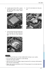
Страница 18: ... cooler fan for better heat dispersion Follow the steps below to install the CPU cooler correctly Wrong installation will cause the damage of your CPU mainboard Open the load level 1 Lift the load lever up and open the load plate 2 The CPU socket has a plastic cap on it to protect the contact from damage Before you install CPU always cover it to protect the socket pin Romove the cap from the lever...

Страница 19: ...and then secure the lever with the hook under retention tab 7 Important Confirm if your CPU cooler is firmly installed before turning on your system Do not touch the CPU socket pins to avoid damage Read the CPU status in BIOS Whenever the CPU is not installed always protect the CPU socket pin with the plastic cap covered to avoid damage Please refer to the documentation in the CPU fan package for ...

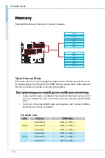
Страница 20: ...d through the memory modules in an alternating pattern Three independent memory channels give two possible modes of interleaving Triple channel mode is enabled when identical matched memory mod ules are installed in each of the three memory channels black DIMM slots If only two of the black DIMM slots are populated with matched DIMMs dual channel memory is enabled Channel List CPU Channel DIMM Slo...

Страница 21: ...until the golden finger on the memory module is deeply inserted in the DIMM slot The plastic clip at each side of the DIMM slot will automatically close when the memory module is properly seated Manually check if the memory module has been locked in place by the DIMM slot clips at the sides Important You can barely see the golden finger if the memory module is properly inserted in the DIMM slot No...

Страница 22: ... V CHB_1 V V V CHC_0 V V CHC_1 V CHD_0 CHD_1 CHE_0 CHE_1 CHF_0 CHF_1 Dual CPUs Installed CPU0 CPU1 Number of DIMMs installed 1 2 3 4 5 6 7 8 9 10 11 12 CHA_0 V V V V V V V V V V V V CHA_1 V V V V V V V V V V CHB_0 V V V V V V V V CHB_1 V V V V V V CHC_0 V V V V CHC_1 V V CHD_0 V V V V V V V V V V V CHD_1 V V V V V V V V V CHE_0 V V V V V V V CHE_1 V V V V V CHF_0 V V V CHF_1 V ...

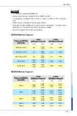
Страница 23: ... Support Ranks per DIMM Data Width 1 DPC DIMM per Channel 2 DPC DIMM per Channel 1 35V 1 5V 1 35V 1 5V SRx8 Non ECC n a 1066 1333 n a 1066 DRx8 Non ECC n a 1066 1333 n a 1066 SRx16 Non ECC n a 1066 1333 n a 1066 SRx8 ECC 1066 1333 1066 1333 1066 1066 DRx8 ECC 1066 1333 1066 1333 1066 1066 RDIMM Module Support Ranks per DIMM Data Width 1 DPC DIMM per Channel 2 DPC DIMM per Channel 1 35V 1 5V 1 35V ...

Страница 24: ...Hardware Setup Hardware Setup LV DIMM Module Support Ranks per DIMM Data Width 1 DPC DIMM per Channel 2 DPC DIMM per Channel 1 35V 1 5V 1 35V 1 5V SRx8 1066 1066 1333 1066 1066 DRx8 1066 1066 1333 1066 1066 ...

Страница 25: ...0081 2 11 MS S0081 Storage Storage Port Location BATT BATT SATA0 SATA1 SATA2 SATA3 SATA4 SATA5 BATT SAS0 Storage Support Comparison Chip PCH SATA 6 Gb s SATA 3 Gb s C602 Patsburg A 2 SATA0 1 8 SATA2 5 SAS0 ...

Страница 26: ...Setup Hardware Setup Storage Speed PCH Port Patsburg A SATA0 SATA 6 Gb s SATA1 SATA 6 Gb s SATA2 SATA 3 Gb s SATA3 SATA 3 Gb s SATA4 SATA 3 Gb s SATA5 SATA 3 Gb s SAS0 SATA 3 Gb s SATA 3 Gb s SATA 3 Gb s SATA 3 Gb s ...

Страница 27: ...2 3 3 V 1 5 G r o u n d 3 G r o u n d 1 6 P S O N 4 5 V 1 7 G r o u n d 5 G r o u n d 1 8 G r o u n d 6 5 V 1 9 G r o u n d 7 G r o u n d 2 2 5 V 1 0 1 2 V 2 0 5 V 8 P W R O K 2 3 5 V 1 1 1 2 V 2 1 5 V 9 5 V S B 2 4 G r o u n d 1 2 3 3 V CPU Power Connector J1 J3 This connector provides 12V power output to the onboard CPU 7 1 2 V 3 G r o u n d 5 1 2 V 1 G r o u n d 8 1 2 V 4 G r o u n d 6 1 2 V 2 ...

Страница 28: ...low Green Orange LED Color LED State Condition Left Yellow Off LAN link is not established On steady state LAN link is established On blinking The computer is communicating with another computer on the LAN Right Green Off 10 Mbit sec data rate is selected On 100 Mbit sec data rate is selected Amber On 1000 Mbit sec data rate is selected USB Port The USB Universal Serial Bus port is for attaching U...

Страница 29: ... wire is Ground and should be connected to GND If the mainboard has a System Hardware Monitor chipset onboard you must use a specially designed fan with speed sensor to take advan tage of the CPU fan control 1 G r o u n d 2 1 2 V 3 S e n s o r 4 C o n t r o l Important Please refer to the recommended CPU fans at processor s official website or consult the vendors for proper CPU cooling fan Fan coo...

Страница 30: ...Serial Attached SCSI Connector SAS0 The SAS connector is a new generation serial communication protocol for de vices designed to allow for much higher speed data transfers It supports data transfer speeds up to 3 Gbit s SAS uses serial communication instead of the parallel method found in traditional SCSI devices but still uses SCSI commands for interacting with SAS devices Each MiniSAS connector ...

Страница 31: ...L T L E D 1 6 S Y S I D L E D 4 S Y S I D L E D 2 F R O N T P A N E L P O W E R 2 1 W I R E T E M P S E N S O R 2 3 N M I S W I T C H 1 0 S Y S F A U L T L E D 2 1 4 N I C 1 A C T L E D 1 8 S M B U S C L K 1 7 R E S E T S W I T C H G N D Front USB Connector USB_P10_P11 USB_P2_P3 USB_P1 This connector compliant with Intel I O Connectivity Design Guide is ideal for connecting high speed USB interfac...

Страница 32: ...o it 1 0 N o P i n 8 R I 6 C T S 4 R T S 2 D S R 1 D C D 3 R X D 5 T X D 7 D T R 9 G N D VGA Connector VGA The VGA connector is provided for monitors 1 1 G N D 9 B P _ C R T _ G R E E N 1 3 B P _ C R T _ B L U E 5 B P _ C R T _ R E D 1 5 V _ V G A _ B H 2 G N D 4 H S Y N C _ H 1 6 G N D 3 G N D 1 2 F _ D D C D A T 7 G N D 8 G N D 6 V S Y N C _ H 1 0 K E Y 1 4 F _ D D C C L K 1 5 G N D ...

Страница 33: ...et the jumper to clear data Normal 1 Clear CMOS 1 CLR_CMOS 1 Important You can clear CMOS by shorting pins 2 and 3 while the system is off Then return to 1 2 pin position Avoid clearing the CMOS while the system is on it will dam age the mainboard BIOS Recovery Jumper J108 Users can short pins 2 and 3 to recover the system BIOS When the system is done with the job the buzzer will beep to remind th...

Страница 34: ... other add on cards that comply with PCI specifications 32 bit PCI Slot Important When adding or removing expansion cards make sure that you unplug the power supply first Meanwhile read the documentation for the expansion card to config ure any necessary hardware or software settings for the expansion card such as jumpers switches or BIOS configuration PCI Interrupt Request Routing The IRQ acronym...

Страница 35: ...m for optimal use Users may need to run the Setup program when An error message appears on the screen at system startup and re quests users to run SETUP Users want to change the default settings for customized features Important Please note that BIOS update assumes technician level experience 3 BIOS Setup ...

Страница 36: ...ars before you respond and you still wish to enter Setup restart the system by turning it OFF and On or pressing the RESET button You may also restart the system by simultaneously pressing Ctrl Alt and De lete keys Important The items under each BIOS category described in this chapter are under continu ous update for better system performance Therefore the description may be slightly different fro...

Страница 37: ...ind a right pointer symbol appears to the left of certain fields that means a sub menu can be launched from this field A sub menu contains additional op tions for a field parameter You can use arrow keys to highlight the field and press Enter to call up the sub menu Then you can use the control keys to enter values and move from field to field within a sub menu If you want to return to the main me...

Страница 38: ...l enhanced features Server Mgmt Use this menu to configure server management features Boot Use this menu to specify the priority of boot devices Security Use this menu to set supervisor and user passwords Save Exit This menu allows you to load the BIOS default values or factory default settings into the BIOS and exit the BIOS setup utility with or without changes ...

Страница 39: ...ss Level These items show the firmware and hardware specifications of your system Read only System Date This setting allows you to set the system date The date format is Day Month Date Year System Time This setting allows you to set the system time The time format is Hour Min ute Second ...

Страница 40: ...3 6 BIOS Setup BIOS Setup Advanced CPU Configuration ...

Страница 41: ... Intel Virtualization Technology Virtualization enhanced by Intel Virtualization Technology will allow a platform to run multiple operating systems and applications in independent partitions With virtualization one computer system can function as multiple virtual sys tems South Bridge Configuration SOL Setting To enable SOL function COM1 Console Redirection must be enabled ...

Страница 42: ...enables disables the SATA RAID option ROM Power Management Configuration ACPI Sleep State This setting specifies the power saving modes for ACPI function If your oper ating system supports ACPI you can choose to enter the Standby mode in S1 fashion through the setting of this field Restore AC Power Loss This setting specifies whether your system will reboot after a power failure or interrupt occur...

Страница 43: ... S0081 Hardware Monitor Information This menu shows BMC information and hardware monitor status SATA Configuration SATA Mode Serial ATA Controller 0 1 This setting specifies the SATA controller mode SAS Configuration ...

Страница 44: ... EHCI Enhanced Host Controller Interface hand off support The Enhanced Host Controller Interface EHCI specification describes the register level interface for a Host Controller for the Universal Serial Bus USB Revision 2 0 Port 60 64 Emulation This field allows you to enable disable the USB Port 64 60 Emulation function When the function is enabled the USB keyboard is allowed to type some special ...

Страница 45: ...ial Port Console Redirection Console Redirection Console Redirection operates in host systems that do not have a monitor and keyboard attached This setting enables disables the operation of console re direction When set to Enabled BIOS redirects and sends all contents that should be displayed on the screen to the serial COM port for display on the terminal screen Besides all data received from the...

Страница 46: ...bits parity stop bits of Console Redirection Flow Control Flow control is the process of managing the rate of data transmission be tween two nodes It s the process of adjusting the flow of data from one device to another to ensure that the receiving device can handle all of the incoming data This is particularly important where the sending device is ca pable of sending data much faster than the re...

Страница 47: ...e Log This setting offers options for erasing Smbios event logs Erasing is done prior to any logging activation during reset When Log is Full This setting offers options for reactions to a full Smbios event log System Event Log Note All values changed here do not take effect until the computer is restarted SEL Components This setting enables disables system event log components Erase SEL This sett...

Страница 48: ...Log EFI Status Codes This setting offers options for logging EFI status codes BMC Network Configuration Configuration Address Source This setting selects whether to configure LAN channel parameters statically or dynamically DHCP ...

Страница 49: ...instead of the full screen logo Please note that enabling this BIOS feature often adds 2 3 seconds of delay to the booting sequence This delay ensures that the logo is displayed for a suf ficient amount of time Therefore it is recommended that you disable this BIOS feature for a faster boot up time CSM Support This setting enables disables the support for Compatibility Support Module a part of the...

Страница 50: ...Users will be prompted for Administrator password only when they enter BIOS Setup User Password User Password controls access to the system at boot and access to the BIOS Setup utility Users will be prompted for User password when they power on the system or enter BIOS Setup In BIOS Setup users will have Administrator rights ...

Страница 51: ... all changes and reset the system Save Changes Save all changes and continue with the Setup Utility Discard Changes Abandon all changes and continue with the Setup Utility Restore Defaults Restore the factory defaults Save as User Defaults Save all changes as the user defaults Restore User Defaults Restore the preset user defaults ...

Страница 52: ...2 4 1 This chapter provides information on system drivers and utilities Important Please note that firmware update assumes technician level experience 4 Drivers Utilities ...

Страница 53: ...ive The installation will auto run simply click the driver or utility and follow the on screen instructions to complete the installation Important Please visit the MSI website to get the latest drivers and BIOS for better system performance Server Drivers This menu provides available drivers Install the drivers at your desire to activate the installed devices ...

Страница 54: ...MS S0081 4 3 MS S0081 Manual A user s manual in PDF format can be acquired through this menu Download Website Visit the MSI website for technical guides BIOS updates driver updates and other information ...

Отзывы: