


Titan Quick Start Guide
8
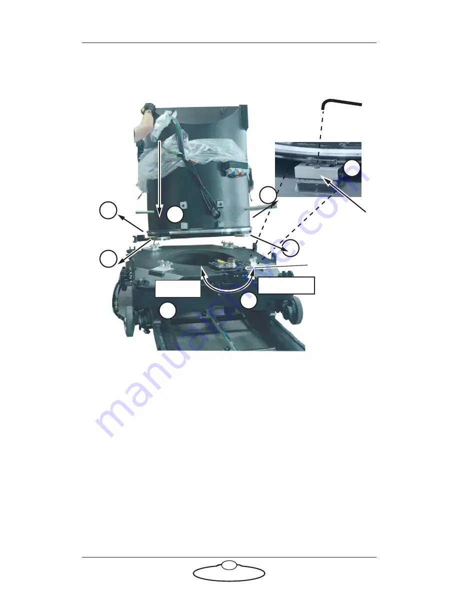
Mounting the turret
1.
Make sure the rotation motor lever is in the anti-clockwise
(Disengaged) position.
2.
Make sure all four turret bolt retainers are fully extended outward.
3.
Lower the turret onto the base. Ensure that the slip rings line up
with the motor connectors.
4.
Press the four turret bolt retainers all the way into the turret, and
tighten the bolts down into the base.
5.
Move the rotation motor lever to the Engaged position taking care
that the gears underneath the turret mesh correctly.
Rotation motor
lever
2
5
Disengaged
Engaged
2
4
Press in
3
1
Turret
Base
2
2
Содержание MRMC-1479-00
Страница 3: ...iii...
Страница 5: ...Titan Quick Start Guide iv...
Страница 35: ...Titan Quick Start Guide 30 Notes...
Страница 36: ...Titan Quick Start Guide 31 Notes...