MESSTEC Power Converter GmbH
Operating Manual
TEC Controller
Document: 10100920OM
Revision: 1.1
Date: 10.10.2019
Page 15/71
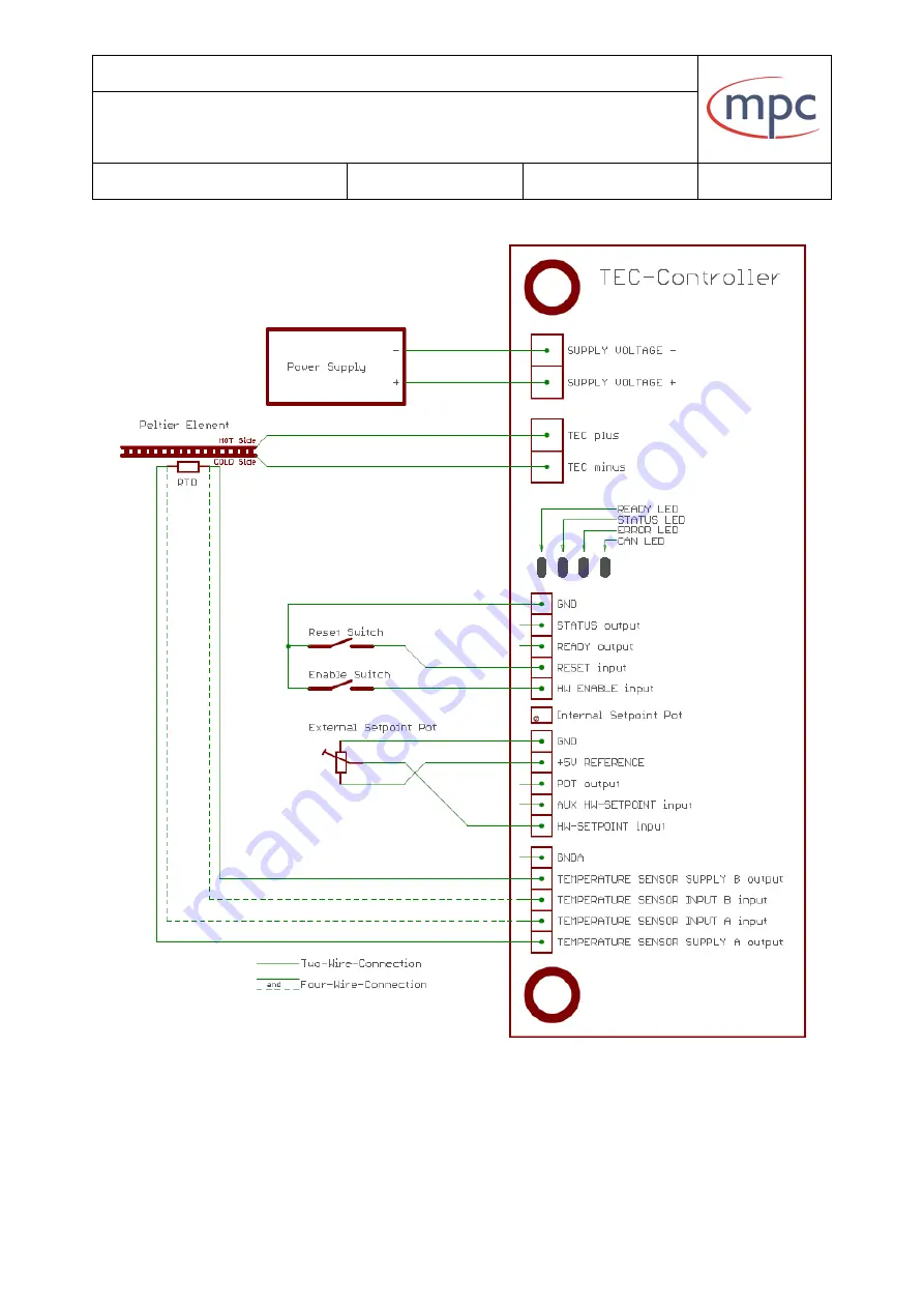
Fig. 7: Wiring example with external setpoint potentiometer
Страница 1: ...00920OM Revision 1 1 Date 10 10 2019 Page 1 71 Revision 1 1 Created Approved Released Form 10 10 2019 OWa 17 10 2019 KS 17 10 2019 KS Distribution File TEC 24 50 TEC 03 50 Warning Risk of exposure of hazardous laser radiation in combination with laser light emitting devices ...
Страница 2: ...ensor 24 5 6 Sensor Current 26 6 Indicator elements 27 6 1 Indication of operating states 27 6 1 1 Indicator LEDs 27 6 1 2 Booting sequence 28 6 1 3 Safe State during configuration of digital Inputs Outputs 29 6 2 Indication of serial data transfer 29 6 3 Monitoring of supply voltages 30 7 Wiring and connectors 31 7 1 Hookup groups 31 7 2 Connectors and signals 32 7 2 1 Supply Voltage X5 32 7 2 2 ...
Страница 3: ...ts and Outputs 49 8 2 1 Inputs 49 8 2 2 Outputs 50 9 Error states 51 9 1 SENSOR Error 51 9 2 OVERTEMPERATURE Error 52 9 3 SHORTCIRCUIT Error 52 10 PC Software TEC Control 53 10 1 Main menu 53 10 2 Configuration 57 10 2 1 Temperature limits 58 10 2 2 Current limit 59 10 2 3 Voltage limit 59 10 2 4 Boundary Mode 60 10 2 5 Sensor selection 60 10 2 6 Control parameter 61 10 2 7 Enable Mode 62 10 2 8 S...
Страница 4: ...MESSTEC Power Converter GmbH Operating Manual TEC Controller Document 10100920OM Revision 1 1 Date 10 10 2019 Page 4 71 11 3 Version 3 A 69 12 TEC Controller family 70 ...
Страница 5: ... to 50V from MPC are available in 4 output current ranges up to 3A output current up to 6A output current up to 12A output current up to 24A output current TEC Controllers from MPC can be operated in various modes Hardware only Software only combination of hardware and software control TEC Controllers from MPC are standalone Figure 1 shows a minimal system Fig 1 Minimal TEC Controller System For a...
Страница 6: ... Operating Manual TEC Controller Document 10100920OM Revision 1 1 Date 10 10 2019 Page 6 71 There is a PC Software available which provides access to comprehensive configuration control and live monitoring menus Fig 2 PC Software ...
Страница 7: ...rating voltage current of half of the maximum operating voltage current Orientation of the Peltier Element in the mechanical setup COLD side towards diode or heatspreader and temperature sensor HOT side towards heatsink Never use any of the gold plated contact pads as mounting holes for mechanical fixture see red arrows These contact pads are connected to internal power supplies and control signal...
Страница 8: ...rect polarity With high efficiency the input voltage is processed by the power stage according to the digital temperature controller After extensive filtering in two stages the resulting voltage is applied to the terminal for the Peltier element The Peltier element is driven by a DC signal The current ripple is below 1 The power stage is protected by a short circuit detector which is implemented i...
Страница 9: ...essing circuit ensures very high precision and virtu ally no drift errors There is no need for calibration Signal processing for the temperature sensor has open sensor and short circuit detection In either case the TEC Controller goes into error mode and will be disabled For TEC Controller operation there are 3 sorts of control signals and corresponding sig nal processing available analog input wi...
Страница 10: ...DY output will be deactivated The digital output STATUS will be activated when the TEC Controller is enabled and if the sensor temperature is within 1 C of the setpoint value The serial interface is carried out by standard USB 2 0 Mini B connector TEC Controllers are available in two different hardware versions with USB Interface or with RS232 Inter face Both interface types are operating with the...
Страница 11: ...eatspreader also called cooling plate is a solid block made of copper or aluminum Usually the base area of the heatspreader is larger than that of the Peltier Element because of the required mounting holes The temperature sensor is positioned inside the heatspreader For this purpose an appropriate hole or notch has to be machined into the heatspreader directly below the laser diode Make sure the t...
Страница 12: ...e is aligned towards the heatsink Wrong assembly will yield in total malfunction and instability of the system and may further damage your setup Finally with its hot side the Peltier Element is mounted to the heatsink Make sure the heatsink is designed large enough to well dissipate all the heat produced in the system setup Pay attention that all joints within the heat flow feature lowest possible...
Страница 13: ...if the TEC Controller is operated by PC Software there is also a Reset button available in the GUI In the following some sample applications are shown Figure 6 The internal setpoint potentiometer is applied Therefore a simple wire bridge must be installed Figure 7 An external setpoint potentiometer is installed Please also note chapter Wiring examples for the analog input CA SETPOINT Figure 8 The ...
Страница 14: ...MESSTEC Power Converter GmbH Operating Manual TEC Controller Document 10100920OM Revision 1 1 Date 10 10 2019 Page 14 71 Fig 6 Wiring example with internal setpoint potentiometer ...
Страница 15: ...MESSTEC Power Converter GmbH Operating Manual TEC Controller Document 10100920OM Revision 1 1 Date 10 10 2019 Page 15 71 Fig 7 Wiring example with external setpoint potentiometer ...
Страница 16: ...MESSTEC Power Converter GmbH Operating Manual TEC Controller Document 10100920OM Revision 1 1 Date 10 10 2019 Page 16 71 Fig 8 Wiring example HW ENABLE input is high active ...
Страница 17: ...MESSTEC Power Converter GmbH Operating Manual TEC Controller Document 10100920OM Revision 1 1 Date 10 10 2019 Page 17 71 Fig 9 Wiring example setpoint mode via Control Software ...
Страница 18: ...MESSTEC Power Converter GmbH Operating Manual TEC Controller Document 10100920OM Revision 1 1 Date 10 10 2019 Page 18 71 Fig 10 Wiring example external READY and STATUS LEDs ...
Страница 19: ...MESSTEC Power Converter GmbH Operating Manual TEC Controller Document 10100920OM Revision 1 1 Date 10 10 2019 Page 19 71 Fig 11 Wiring example external READY and STATUS relays ...
Страница 20: ...e system For wiring details please see chapter Wiring and connectors Temperature Sensor X4 The type of sensor applied in the setup can be configured by means of PC Software Note The default sensor type is Pt1000 5 1 Platinum Sensor In the PC Software Pt1000 and Pt100 Sensors are available It is not necessary to enter any coefficients just press the button for the sensor in your application see fi ...
Страница 21: ...cients just press the button for the sensor in your application see fi gure 13 below Fig 13 Nickel sensor selection Supplementary detailed information Nickel Sensors have a characteristic curve according to 𝑅 𝜗 𝑅𝜗0 1 𝑎 𝜗 𝜗0 𝑏 𝜗 𝜗0 2 𝑐 𝜗 𝜗0 4 𝑑 𝜗 𝜗0 6 a 5 485 10 3 C 1 b 6 650 10 6 C 2 c 2 805 10 11 C 4 d 2 00 10 17 C 6 ϑ Temperature in C ϑ0 Reference temperature in C ϑ0 0 C for Nickel Rϑ0 Reference...
Страница 22: ...l able from the device datasheet see figure 14 below Fig 14 NTC sensor parameters Supplementary detailed information NTC sensors have a characteristic curve according to 𝑅𝜗 𝑅𝑟𝑒𝑓 𝑒 𝐵 1 𝜗 1 𝑇𝑟𝑒𝑓 Rref Reference resistor value in Ω B Beta value in K ϑ Temperature in K Tref Reference temperature in K Note The TEC Controller firmware always converts Kelvin to Celsius The user never has to hassle with Ke...
Страница 23: ...ssary to en ter any coefficients just press the button for the sensor in your application see figure 15 below Fig 15 Silicone sensor selection Supplementary detailed information Silicon Sensors have a characteristic curve according to 𝑅 𝜗 𝑅𝜗0 1 𝑎 𝜗 𝜗0 𝑏 𝜗 𝜗0 2 a 7 880 10 3 C 1 b 1 937 10 5 C 2 ϑ Temperature in C ϑ0 Reference temperature in C ϑ0 25 C for KTY11 sensors Rϑ0 Reference resistor value i...
Страница 24: ...𝜗 𝜗0 3 𝑎4 𝜗 𝜗0 4 𝑎5 𝜗 𝜗0 5 𝑎6 𝜗 𝜗0 6 a1 coefficient 1st order unit C 1 a2 coefficient 2nd order unit C 2 a3 coefficient 3rd order unit C 3 a4 coefficient 4th order unit C 4 a5 coefficient 5th order unit C 5 a6 coefficient 6th order unit C 6 ϑ Temperature in C ϑ0 Reference temperature in C Rϑ0 Reference resistor value in Ω Rϑ0 R ϑ at ϑ0 The configuration of arbitrary sensors allows a high degree of...
Страница 25: ...19 Page 25 71 In the PC Software the arbitrary sensor can be configured according to figure 16 and 17 To select a coefficient click on the value right side of a coefficient The default setting corresponds to the sensor Pt1000 Fig 16 Arbitrary sensor definition page 1 Fig 17 Arbitrary sensor definition page 2 ...
Страница 26: ...on Minimized sensor power hence self heating Sensor signal processing has upper and lower limits It is a common rule of thumb to limit the load of the sensor to 1 mW With this value self heating of the sensor device is acceptable low and the sensor output signal is high enough for precision signal processing Sensor signal processing limits are UMIN 0 08 V UMAX 2 30 V Sensor voltages below UMIN are...
Страница 27: ...ansfer Monitoring of supply voltages 6 1 Indication of operating states 6 1 1 Indicator LEDs Fig 18 Operating states indicator LEDs CAN LED Currently not used ERROR LED Indication of error states LED Off no error LED one flash Sensor error short circuit or open sensor wiring LED two flashes Output current too high external short circuit LED three flashes internal over temperature of power stage De...
Страница 28: ...and the booting sequence this LED is blinking periodically indicating the processor is working properly The TEC Controller is operating normally Note If this LED shows different behavior the TEC Controller is not operating normally Do NOT enable the TEC Controller in this case 6 1 2 Booting sequence After power up the processor runs through a booting sequence During this se quence the internal and...
Страница 29: ...ng of three LEDs RED YELLOW GREEN The Safe State can be left only by switching off the power supply of the TEC Controller 6 2 Indication of serial data transfer Fig 19 Serial data transfer indicator LEDs During serial data transfer USB or RS232 to PC or external controller these LEDs are flashing accordingly RXD flashing data is being received TXD flashing data is being transmitted While connected...
Страница 30: ... are possibilities for monitoring internal supply voltages In any case all LEDs must be constantly ON LED 1 5 V sensor signal processing LED 2 5 V i o reference voltage LED 3 3 3 V LED 12 5 V LED 13 12 V LED 14 6 V Note LED 2 monitors the reference voltage for the HW SETPOINT If this LED is Off double check the wiring of the external setpoint potentiometer The reference voltage may be short circui...
Страница 31: ...groups Three groups of hookups are available to operate the TEC Controller Power large screw type connectors Control and temperature sensor small screw type connectors PC interface USB 2 0 Mini B connector Fig 21 Hookup groups DC Power INPUT Peltier element OUTPUT Digital Control IN OUTPUT Analog Control IN OUTPUT Temperature Sensor Interface USB Connector ...
Страница 32: ...ew terminal Temperature sensor USB RS232 USB 2 0 Mini B connector 7 2 1 Supply Voltage X5 Pin Name Function 1 SV Supply voltage plus 2 GND Power GND supply voltage minus SV X5 1 Supply voltage plus Supply voltage 15 0 V 48 0 V max 50 V Supply current depends on the output load max 15A There are no internal fuses The supply voltage has to be fused external Supply voltage should be approx 10 above m...
Страница 33: ... control situation and is not related to GND Warning Do not connect to GND or any other electrical potential TECplus X6 2 Connection to Peltier element plus Voltage 0 V Supply voltage This output pin has to be connected to the plus pin of the Peltier element It does not mean that there is a positive voltage related to the output pin TECminus The polarity on this outputs is dependent exclusively on...
Страница 34: ...ut X2 1 Control Digital HW ENABLE Hardware Enable Input resistance 10 kΩ pullup Digital TTL 5 V input High if left open Default configuration low active A low signal or pulling HW ENABLE to GND will start the temperature controller and the output power stage The TEC Controller is then fully activated and starts temperature regulation For safety reasons this signal is essential in any case Even if ...
Страница 35: ...left open Default configuration low active With HW RESET internal error states can be cleared see Error states Note The HW RESET input is not a reset line for the MCU CD READY Output X2 3 Control Digital READY Output resistance 330 Ω Digital TTL 5 V output Default configuration high active The output signal READY indicates that the TEC Controller is working normally and that there are no error sta...
Страница 36: ... Digital STATUS Output resistance 330 Ω Digital TTL 5 V output Default configuration high active STATUS inactive TEC Controller is disabled OR sensor temperature is outside 1 C of the setpoint value STATUS active TEC Controller is enabled AND sensor temperature is within 1 C of the setpoint value GND X2 5 Signal GND Reference potential for CD signals ...
Страница 37: ...e feed into this input sets the hardware setpoint of the temperature controller Voltage sources for this purpose are Internal potentiometer External potentiometer Voltage controller Wiring examples see below Note The HW SW SETPOINT MODE has to be set to HW by means of the PC Software This is the default mode The target temperature in C is proportional to the voltage according to the following rela...
Страница 38: ...sion 1 1 Date 10 10 2019 Page 38 71 CA POT Output X1 3 Control Analog Output of built in setpoint potentiometer Output resistance 1 kΩ REFERENCE 5V Output X1 4 Control Analog Output of reference voltage 5 V Output current Imax 100mA GND X1 5 Signal GND Reference potential for CA signals ...
Страница 39: ...nboard This potentiometer is already connected internally to the reference voltage and GND The only external connection has to be made between CA POT and CA SETPOINT see figure 23 below Fig 23 Wiring of internal setpoint potentiometer 7 2 5 2 External Potentiometer with reference voltage A simple way to control the HW Setpoint from a remote position is to place a potentiometer 1kΩ linear in the se...
Страница 40: ... 5 3 Voltage Controller An external voltage controller i e Digital to Analog Converter can be provided as HW Setpoint source Wiring is according to figure 0x Specification of the voltage controller Output voltage 0 V 5 V Output impedance 1 kΩ max Output must be galvanically isolated Fig 25 Wiring external voltage controller ...
Страница 41: ...A potential difference on the sensor inputs below 0 08 V short circuit or above 2 35 V open circuit will release a SENSOR Error Pin Name Function 1 TS SUPP A Temperature Sensor Supply A 2 TS SENS A Temperature Sensor Input A 3 TS SENS B Temperature Sensor Input B 4 TS SUPP B Temperature Sensor Supply B 5 GNDA Analog Signal GND TS SUPP A X4 1 Temperature Sensor Supply A Current Source Contact A Use...
Страница 42: ...ase of significant EMI Electromagnetic Interference Fig 26 Sensor cabling 4 Wire Note Never mix up A and B pins At the sensor end of the cable signal TS SUPP A has to be combined only with TS SENS A The same is true for the B signals of the interface 2 Wire Sensor cabling For temperature measurements with lower requirements it may be adequate to apply 2 wire cabling of the temperature sensor It is...
Страница 43: ...nal controller PLD or MCU USB interface The TEC Controller has a built in USB 2 0 Mini B connector For connection use standard USB cable Mini B male to Standard A male ordering code 10385120 Mini B male to Type C male ordering code 11385247 RS232 interface Serial port settings Baud rate 38400 Data length 8 Bit Parity none Stop 1 Bit Flow control none Use RS232 interface cable USB Mini B to SubD9F ...
Страница 44: ...ignals are galvanically isolated from the TEC Controller electronics Note TEC Controllers with RS232 interface are using the built in Mini B con nector as hardware connecting plug In this case the MINI B connector does not carry USB signals and should never be connected to the USB port of any PC The USB port of the PC may be damaged ...
Страница 45: ... shows the basic transfer function with no minimum and maximum temperature set default setting Fig 29 Basic transfer function The red curve shows the relationship between HW Setpoint Voltage input voltage and the temperature setpoint With default settings minimum temperature 0 C maximum temperature 50 C the relationship is linear Example A voltage of 2 V at the input CA SETPOINT will lead to a set...
Страница 46: ...perature the relationship is like in basic mode Below min and above max temperature the transfer function is running horizontal see solid red line in figure 30 below Fig 30 Clipping mode transfer function Example see figure 30 above Supposed min temperature is set to 20 C and max temperature is set to 30 C by PC Software then a HW Setpoint Voltage between 2 V and 3 V leads to a temperature setpoin...
Страница 47: ...mation In this mode the relationship between the HW Setpoint Voltage and the tem perature setpoint is still linear but has a different slope than the basic transfer function Now a HW Setpoint Voltage of 0 V leads to a setpoint of min tempe rature and 5 V lead to a setpoint of max temperature see solid red line in fi gure 31 below This means the complete input voltage range is used Fig 31 Slope tra...
Страница 48: ... 𝑆𝐸𝑇𝑃𝑂𝐼𝑁𝑇 5 0 𝜗𝑀𝐴𝑋 𝜗𝑀𝐼𝑁 𝜗 𝜗𝑀𝐼𝑁 For purpose of illustration the basic transfer function is also shown in figu re 31 dashed red line It is apparent that the slope of the transfer function has changed it is transformed to the actual min and max temperature values Advantage The usable adjustment range potentiometer or voltage source is always the full range 0 V to 5 V Disadvantage The relationship bet...
Страница 49: ...l inputs and outputs can be carried out by PC Soft ware There is no need to modify the hardware 8 2 1 Inputs Digital inputs are compatible to TTL and can be configured as LOW active HIGH active The default setting is LOW active Supplementary detailed information A pullup or pulldown resistor 10 kΩ will be internally connected accordingly see figure 32 below Fig 32 Digital input circuit ...
Страница 50: ...urthermore the output stage can be configured as Totem Pole push pull Open Collector The default setting is Totem Pole When set to Totem Pole the output resistance is 330Ω When set to Open Collector the output resistance is very low 0 5 Ω In this case the output can sink up to 500 mA and is short circuit protected Note Also in Open Collector configuration the output voltage coming from the externa...
Страница 51: ... LED is flashing periodically 1 short flash SENSOR Error 2 short flashes SHORTCIRCUIT Error 3 short flashes OVERTEMPERATURE Error To clear an error do follow the indicated procedure disable HW ENABLE input troubleshoot the cause of the error activate HW RESET input error state is cleared Now the TEC Controller is ready for normal operation again It is also possible to clear an error by clicking th...
Страница 52: ...perature is below 75 C again this error can be cleared by Reset signal Ensure sufficient cooling if necessary 9 3 SHORTCIRCUIT Error When the output current of the power stage exceeds a certain level a SHORTCIR CUIT Error is released The short circuit detector is implemented in hardware and therefore reacting fast no software latency In this way the output stage is protect ted from damage Under no...
Страница 53: ...mouse With the TEC Control Software it is possible to configure control monitor MPC TEC Controllers extensively TEC Control Software is separately available Ordering Code 31000055 10 1 Main menu To start the program double click the MPCTEC icon If there is available more than one COM Port on your PC during startup you will be asked to select the COM Port where the TEC Controller is connected to Fi...
Страница 54: ... TEC Controller In the middle region of the menu there is displayed actual sensor temperature actual output current actual output voltage The temperature setpoint is displayed on the left side If setpoint mode is set to hardware see configuration this value is set by the analog voltage at the input HW SETPOINT If setpoint mode is set to software a single mouse click into the display opens a menu w...
Страница 55: ...ernal safety signal Final EN is dependent on the ENABLE MODE and the input signal HW ENABLE see chapter Control Signals Digital X2 and Configuration HW EN is reflecting the state of the input signal HW ENABLE The status bar at the bottom shows the general condition of the TEC Controller TEC Controller is working fine there are no errors If the TEC Controller is enabled then Ok means the sensor tem...
Страница 56: ...button opens the Configuration menu see Configuration Note The Config button is only active when the TEC Controller is disabled End button quits the PC Software It is possible to show the temperature profile in a graphic chart With Show Graph and Hide Graph the chart is opened or closed respectively Axes are scaled automatically On the bottom of the Graph it is possible to choose an averaging fact...
Страница 57: ...possible to enter the configuration menu only if the TEC Controller is disabled Below the buttons the selected and active configuration is displayed In most menus the desired value is set by clicking the up or down arrow buttons accordingly In the lower part of the configuration menu the same monitoring values are being displayed as in the main menu see section Main menu ...
Страница 58: ...10100920OM Revision 1 1 Date 10 10 2019 Page 58 71 10 2 1 Temperature limits Click this button to open the next menu Here it is possible to set temperature limits Note MIN Temperature must be at least 1 C below MAX Tempe rature Only then it is possible to confirm with Ok ...
Страница 59: ...lick this button to open the next menu Here it is possible to set the maximum output current Note Lowest setting is 1 A Highest setting is dependent of the type of TEC Controller 10 2 3 Voltage limit Click this button to open the next menu Here it is possible to set the maximum output voltage Note Lowest setting is 1 V Highest setting is 48 V ...
Страница 60: ... Page 60 71 10 2 4 Boundary Mode Click this button to change the setting of the HW Setpoint Boundary Mode See also Configuration in Detail HW Setpoint 10 2 5 Sensor selection Click this button to open the next menu Here it is possible to select the temperature sensor in use See also section Temperature sensor ...
Страница 61: ...ntegral component of the control loop kd Coefficient of the derivative component of the control loop Note kd is used only in very rare and exceptional cases In most cases it is not necessary to alter control coefficients If you do need to make adjustments to control coefficients consider small steps and double check the result after each step Note Modifications of control coefficients in the wrong...
Страница 62: ...on is active when the input signal HW Enable is disabled Note When enable mode is set to hardware the Start button in the main menu is not active 10 2 8 Setpoint Mode Click this button to change the setpoint mode between hardware and software That is the way the desired temperature is determined and entered into the TEC Controller Hardware An analog voltage which is proportional to the setpoint te...
Страница 63: ...H active Digital outputs LOW active HIGH active Totem pole push pull Open collector See also section Configuration in Detail Digital inputs and Outputs Example Changing the input CD ENABLE from active LOW to active HIGH Configurations in this domain generally have big influence to the control behavior of the TEC Controller and its setup To avoid damage and mal function in any case the TEC Controll...
Страница 64: ...arning message will appear Once you are certain you know what you are doing click the continue button Now you can select the configuration of digital inputs and digital outputs as desired Please follow the advice displayed in the window After pressing the OK button the TEC Controller will go into a save state This is normal procedure a safety measure and NOT an error state ...
Страница 65: ...tware will be terminated automatically Next disconnect the TEC Controller from the power supply Change the wiring and control logic configuration of your setup according to the just altered IO configuration of the TEC Controller Switch on the power supply of the TEC Controller again Start the PC Soft ware again Now the setup and the TEC Controller is operating with the new IO configura tion ...
Страница 66: ...ument 10100920OM Revision 1 1 Date 10 10 2019 Page 66 71 10 3 USB Driver When the TEC Controller USB version is connected to the PC for the first time the correct USB driver will be installed automatically In any case the correct USB driver is located on the CD ROM ...
Страница 67: ...MESSTEC Power Converter GmbH Operating Manual TEC Controller Document 10100920OM Revision 1 1 Date 10 10 2019 Page 67 71 11 Drawings 11 1 Version 12 A and 24 A ...
Страница 68: ...MESSTEC Power Converter GmbH Operating Manual TEC Controller Document 10100920OM Revision 1 1 Date 10 10 2019 Page 68 71 11 2 Version 6 A ...
Страница 69: ...MESSTEC Power Converter GmbH Operating Manual TEC Controller Document 10100920OM Revision 1 1 Date 10 10 2019 Page 69 71 11 3 Version 3 A ...
Страница 70: ...e 10100130 TEC 6 50 B R TEC 6A with RS232 interface 10100131 TEC 12 50 B U TEC 12A with USB interface 10100135 TEC 12 50 B R TEC 12A with RS232 interface 10100136 TEC 24 50 B U TEC 24A with USB interface 10100140 TEC 24 50 B R TEC 24A with RS232 interface 10100141 RS232 interface cable USB Mini B to SubD9F adapter cable 10385263 USB cable Mini B to Standard A cable 10385120 USB cable Mini B to Typ...
Страница 71: ... Document 10100920OM Revision 1 1 Date 10 10 2019 Page 71 71 Contact Data MESSTEC Power Converter GmbH Grube 41 D 82377 Penzberg Phone 49 0 8856 80306 0 Fax 49 0 8856 9998 info powerconverter com www powerconverter com Technical subjects to change without notice ...