background image


USER MANUAL   

S E M S  


- 17 - 


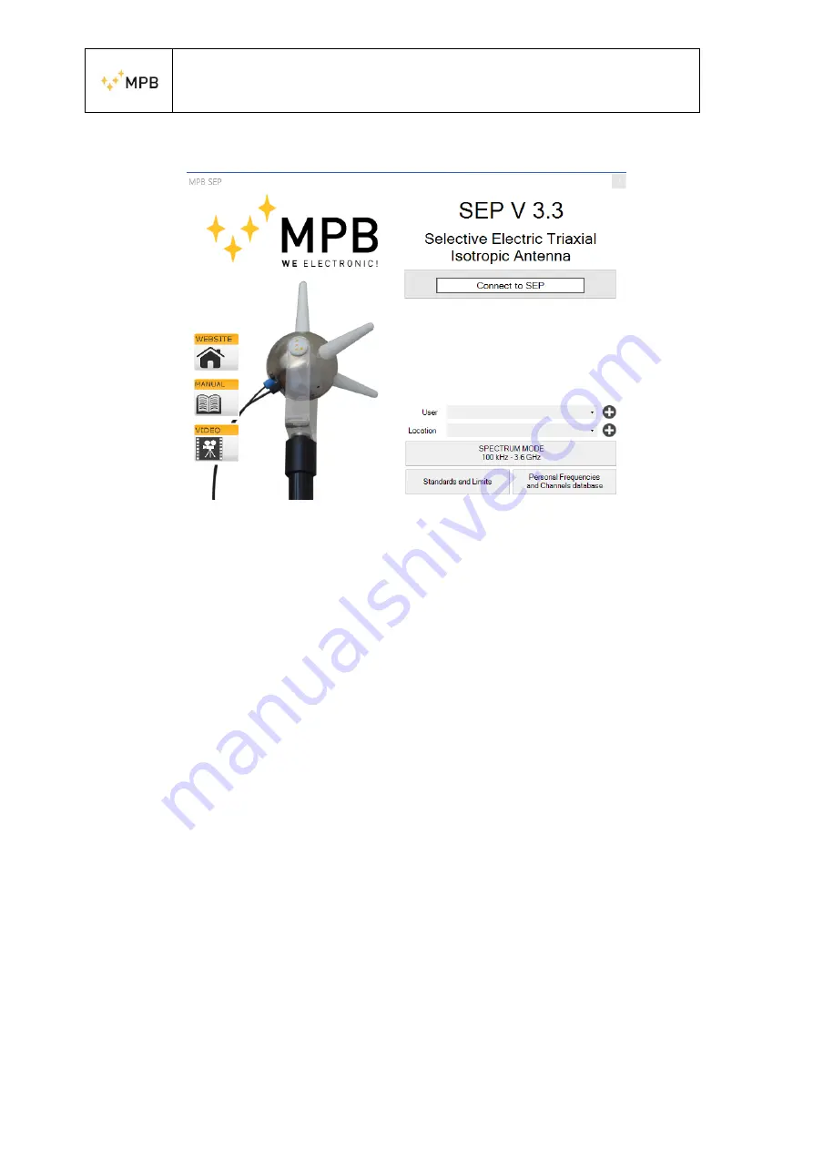
4.5.  Software Home page 


Figure 7 Home Page 


[We recommend a screen resolution of 1920 x 1080 – with 100% screen configuration] 
By  pressing  the  “Connect”  button,  the  software  will  attempt  a  connection  with  the 
device, automatically finding the correct COM port. In case of eventual error message, 
the software will warn the user asking to check the power status of the SEP or the driver 
installation. 
Once the connection is established, a green outline will confirm that the instrument is 
connected  and  ready  to  make  measurements.  The  MPB  SEP  will  show  under  the 
“Connect” button, the device information, such as the COM port used, the FW version 
installed in the device, the serial number, the calibration date, the working mode and 
the battery level. 
Now, with the SEP connected, the “Spectrum Mode” will be enabled. Please note that 
although  the  frequency  range  of  the  instrument  is  100  kHz–3.6  GHz,  two  working 
bands are allowed: “Band1” [100 kHz-9.999MHz] and “Band2” 
[10MHz-3.6GHz]. By default, the instrument’s working mode is set on “Band2”. This 
means that working in between “Band1” and “Band2” (e.g. a start frequency set at 9 
MHz and stop frequency set at 20 MHz) is not allowed. It is recommended to insert 
username and location in order to recall the data both on the graph and generated files. 
On the left part of the panel, also three shortcuts are present: 


Website: direct link to the MPB website 


Manual: offline link to the SEP manual, added during the installation 


Video: direct link to the MPB Youtube page 

 
From the main screen, a measuring mode and two user commodity forms are available. 

Содержание SEP

Страница 1: ... 39 0641200744 Fax 39 0641200653 info gruppompb com www gruppompb uk com SEP user manual V 1 9 User manual SEP Selective Electric Isotropic Triaxial Antenna Updated to software version MPB SEP V 3 3 SEPcfg 1 0 Updated to firmware version SEP B 37 MSP430 2 07 ...

Страница 2: ...andards The instrumentation described in this manual has been produced and tested in conditions that fully comply with the European standards To maintain these conditions please carefully follow this manual This product is intended for industrial environments and laboratories and should be used by authorized personnel only MPB disclaims any responsibility for different uses of the device ...

Страница 3: ... Complies with the following European Standards Safety CEI EN 61010 1 undated reference applies to all editions EMC EN 61326 1 undated reference applies to all editions This product complies with the requirements of the Low Voltage Directive 2014 35 EU and with the EMC Directive 2014 30 EU and the RoHs directive 2011 65 EU MPB S r l ...

Страница 4: ...12 3 2 Placement 13 3 3 Fiber Optic Plug 13 3 4 Switch On Off 13 4 Use and functioning of the software MPB SEP 14 4 1 Prerequisites 14 4 2 NET Framework 4 0 installation 14 4 3 FTDI driver installation 15 4 4 MPB SEP installation 15 4 5 Software Home page 17 4 5 1 Standards and Limits 18 4 5 2 Personal Frequencies and Channels 18 4 6 Spectrum Mode 19 4 6 1 Graphics 20 4 6 2 Snapshot 21 4 6 3 Mouse...

Страница 5: ...ncies 28 4 13 Axis Selection 28 4 14 Measurement tools 30 4 14 1 Markers 30 4 14 2 Multi Channel Power Only in Band2 31 5 APPENDIX A Communication _Protocol 35 6 APPENDIX B WiFi and Bluetooth connection 41 6 1 WiFi connection mod SEP WHD 42 6 2 Bluetooth connection mod SEP WLD 43 6 3 How to verify serial port 46 ...

Страница 6: ...tivity axes allow the SEP to cover different applications in the sector of electric field measurements 1 2 System description The SEP Figure 1 is a small spherical measurement system coming with three antennas of the same size arranged on measurement axes that are perpendicular to each other It is also equipped with a non magnetic stirrup for the fixing a micro USB connector and two connectors for...

Страница 7: ...V 4 x slots battery charger 4x Lithium battery Panasonic model NCR18500 Cap remover User Manual STD Calibration Certificate 1 4 Option WiFi and Bluetooth connection For more information see APPENDIX B 1 5 SEP Overview USB connector Status LED Fiber Optic ON OFF button Figure 2 ...

Страница 8: ... carries 30 kHz carries 300 kHz carries 1 GHz 85 dBc Hz 90 dBc Hz 102 dBc Hz Measurement Range Max Level Min Level 500 kHz Min Level 10 to 100 MHz Min Level 0 1 to 2 GHz Min Level 2 to 3 GHz Min Level 3 to 3 6 GHz Damage Level Dynamic Range 200 MHz Linearity Error 200 MHz 200 v m 10 MHz 3 6 GHz 1 v m 3 kHz RBW HW Detector Average 0 1 v m 3 kHz RBW HW Detector Average 0 02 v m 3 kHz RBW HW Detector...

Страница 9: ... EEPROM Detectors HW Peak AVG and RMS Antenna Three Axial X Y and Z identified by a led Positioned with an axis in vertical or all the axes inclined at 54 7 degrees I O interface Optical Link connector less type USB Bluetooth WiFi Plastic Fiber Cable max length 20mt Micro USB Connector Fiber Bluetooth Adapter distance max 20m in open air WiFi Radio link adpter distance max 300m in open air Operati...

Страница 10: ...mit Orderable in frequency amplitude Root Mean Square value Selects the max value of the isotropic track With selectable time from 1 minute to 1 hour With selectable time from 1 minute to 1 hour Selectable and dragged from 1 MHz to 20 MHz Multiple simultaneous channel power with value acquisition Report Easy screenshots of measurements with the possibility to take notes Setup Programmable customiz...

Страница 11: ...st IF where it is filtered and amplified before being re converted to the frequency of the second IF which makes it downloadable from the analog to digital converter The digital signal as a result of numerous and complex processing is made available to the optical interface that transfers all the necessary data to the PC Through the PC software MPB SEP users will be able to view real time data whi...

Страница 12: ... the cap remover supplied with the kit as shown in Errore L origine riferimento non è stata trovata The Cap remover is equipped with a magnet to help the user with the screwing operation The batteries have to be plugged with the positive side first For recharging the user can remove all the batteries and use the external 220V charger or plug the SEP micro USB connector to a simple charger min 1 Am...

Страница 13: ...ch the optical fiber recognizable by the blue color with the color of the corresponding connector On the side of the PC the USB RS232 converter must be installed with the optical link supplied with the kit In this case there is only one way to connect the optical fiber to the connector For the installation of the converter driver 3 4 Switch On Off To turn on the device press the power button ON OF...

Страница 14: ...d to connect through the fiber optic the SEP to the PC can be installed through the automatic functionality of the Windows driver research or in case of no internet connection using the manual installation mode of the driver also provided in the USB key supplied If the computer meets these requirements and has installed the drivers of the converter you can proceed with the SEP software installatio...

Страница 15: ...he driver supplied with the USB pen driver 4 4 MPB SEP installation Keeping the installer provided in the USB key or downloading the software from our website gruppompb uk com it will be possible to choose in which folder to install the applicative Figure 6 b edit the position of the links in the system menu Figure 6 c In the report Figure 6 d are shown all the settings before proceeding with the ...

Страница 16: ...USER MANUAL S E M S 16 c Link d Report e End Figure 6 Installer MPB SEP ...

Страница 17: ...umber the calibration date the working mode and the battery level Now with the SEP connected the Spectrum Mode will be enabled Please note that although the frequency range of the instrument is 100 kHz 3 6 GHz two working bands are allowed Band1 100 kHz 9 999MHz and Band2 10MHz 3 6GHz By default the instrument s working mode is set on Band2 This means that working in between Band1 and Band2 e g a ...

Страница 18: ...order to favor the expandability and collaboration All standards can be also renamed edited deleted replaced or created from scratch Figure 8 4 5 2 Personal Frequencies and Channels This form allows creating files with frequencies channels users and locations that can then be used when performing measurements for a quick recall to fasten the procedures This form allows making Single Frequencies Li...

Страница 19: ...n the pc through the Apply button Each section has its own Apply button Please note that the Single Frequencies List Files will be shown in the Limit section while Channels List Files will be shown in the Multi Channel Power section see related sections 4 14 2 and 4 14 3 for more information Figure 9 Persona Database 4 6 Spectrum Mode Once the SEP is connected by selecting the Spectrum Mode the sc...

Страница 20: ... group is available it firstly shows or hide by flagging or unflagging the Show related button a default description that can be edited by the user by pressing Edit Description according to his needs Then the Default button will restore on the top of the graph the name and location set before As for the x axis the view can be linear or logarithmic as for the y axis it can be both but is also avail...

Страница 21: ... the actual of the axis data a real time indicator of the axis downloading state The panel moves together with the real data so in case it will not move it means that the scanning is not in progress In that case the operator will have to check if he has pushed the Pause button 4 7 Data Source From this panel the user can select which data source the software will use During the first use the selec...

Страница 22: ...rigger once pressed the user will be warned on the chart informing that recording is going on In this mode every track downloaded by the SEP will be saved on file in the next chapters we will see how to recall this files Level trigger this button will reveal an additional panel for the level selection so the user could set a limit over which the software will save the actual data on file Time trig...

Страница 23: ... and the Data Source panel will show all the recorded files on the pc The data are automatically chronologically sorted by the software By clicking on one of these files the software will load the related session Under the chart are shown date time information for each track through a track bar screen The user will be free to perform new measurements such as channel power markers dragged in a set ...

Страница 24: ... in the Fast Configurations tab The File ITA2016_FastConfiguration mpbc contains all the information concerning the distribution of the frequencies of the TV Radio DAB and mobile frequencies according to the operator updated to the Software release date It is possible to load the configuration files mpbc extension by clicking on Fast Configuration Manage Configurations Import Configurations File a...

Страница 25: ...USER MANUAL S E M S 25 Figure 19 Manage Configurations ...

Страница 26: ...is tab includes three different hardware options on top the Resolution Bandwidth The panel will show all the filters that can be chosen according to the selected frequency range tighter is the span and less will be the filters that can be selected Please note that only for Band1 RBW value is fixed on 3 kHz and cannot be chosen The SEP has six different filters 1 MHz Figure 20 Fast Configurations E...

Страница 27: ...ws choosing from three different modes of acquiring the single point within Peak Average and RMS In the bottom part the Hold Time panel allows to choose how long in milliseconds it takes to consider the measure of each individual point It can be set from a minimum of 0 1 ms to maximum of 10 ms Figure 21 HW Options ...

Страница 28: ...going working band chosen Through the Span tab the measurement range can be set within the selected working band Band1 and Band2 This means that is not possible through the Span values to switch between Band1 and Band2 Please note that in proximity of the limits of the bands the Start Stop and Span values could be automatically re calculated for visu alization purposes Please also note that the RB...

Страница 29: ...sure is available it allows both Average and RMS measures that are mutually exclusive The first one is the average of the summation of different ISO tracks in a set time Please note that by selecting Average in case the user is willing to perform the dragged measure the software will set the hardware detector according to the selection In case he is willing instead to perform the dragged measure b...

Страница 30: ...asure and choose the preferred frequency from the dedicated space or directly from the graph for each marker It is also possible from the graph to move the first marker by left clicking and the second one by right clicking In case of default the tab will include the value of the X Y and Z axes and the Isotropic one If in the session the user has enabled the Max Hold 4 13 visualization and or the A...

Страница 31: ...ed with the name of the preferred personal channel list that will be calculated only in case the selected frequencies belong to the appearing frequency range the calculation will be performed only for the channel powers inside the spectrum otherwise the value will be zero see 4 5 2 By selecting in the dropdown a file name the software will try to adapt available channels in the ongoing scan The Ch...

Страница 32: ...that the MCP total is the RMS summation of all the CP Figure 27 Limits Also in the Limit tab as in the MCP one the Max Hold Average and RMS measurements can be enabled only if they were enabled in the axis selection The Shown Values please note that in the current Software version are allowed up to 30 values in the same scansion combobox will be by default set on Over limits it means that the soft...

Страница 33: ...andards ICNIRP 2010 General Public ICNIRP 2010 Occupational Italy CM 2003 Attention Value Italy CM 2003 Exposure Limits The values obtained can be printed in the three following units of measure V m W 𝑚2 Mw 𝑐𝑚2 percentage value related to the limit according to the frequency The values will be updated at the end of the scansion Moreover the values can be shown ordered by Frequency or Amplitude onl...

Страница 34: ...ntributions By pressing the Recalculate button the limits by frequency will be recalculated and if the station in question does not adhere to the limits selected will be identified the multiplication factors for the reduction in compliance The factor β applies to all sources that individually exceed the limit If despite the first reduction the sum of the contribution is still over the limit the se...

Страница 35: ...the float values represent the numbers in Little Endian notation every float will be contained in 4 bytes every unsigned int will be contained in 2 bytes BASIC REQUEST COMMANDS Commands Description IDN This command IDN gives version and date of the firmware followed by 0D 0A Example of reply IDN SEP FW B 37 20 10 17 0D 0A For a correct configuration of the units use in this sequence the command se...

Страница 36: ...e apparatus internal batteries TBD for future expansions Ric n n if 0 is not recharging or if 1 the internal batteries are recharging USB n n if 0 USB cable not connected if 1 USB cable connected Temp xgr x contains the C apparatus internal temperature Fun c c contains the fan status according to the following bit coding 1 if c 0x01 Fun1 active otherwise not active 1 if c 0x02 Fun1 rotating otherw...

Страница 37: ...AUTO r n Syntax Frequency setting Level 1 Level 2 Level 3 Level 4 SENS FREQ STAR Value expressed in exponential notation that expresses the start frequency in herz ES SENS FREQ STAR 150e3 150000 Hz STOP Value expressed in exponential notation that expresses the stop frequency in herz ES SENS FREQ STOP 300e3 300000 Hz Resolution bandwidth setting Level 1 Level 2 Level 3 SENS BAND AUTO 1 MHz 300 kHz...

Страница 38: ... 2 Level 3 SENS HOLD Hold Time Value expr in mSec minimum 10 maximum 10000 Es SENS HOLD 1500 set the Hold Time at 1 5 seconds Axis Setting Level 1 Level 2 Level 3 SENS AXIS X Y Z Data Request Start data transmission on the series Level 1 Level 2 Level 3 DATA ISTA VERB Response to instant data request in VERBose format ...

Страница 39: ... 025e 08 Hz Fstep 5 000e 04 Hz N level 101 000000 V m 0 02 0 03 0 02 0 03 0 02 0 02 0 01 0 01 0 01 0 01 0 01 0 01 0 01 0 01 0 01 0 01 0 01 0 01 0 01 0 01 0 02 0 02 0 02 0 03 0 03 0 03 0 02 0 01 0 01 0 01 0 01 0 01 0 01 0 01 0 01 0 01 0 01 0 01 0 01 0 01 0 01 0 01 0 01 0 01 0 01 0 01 0 01 0 01 0 01 0 01 0 01 0 01 0 01 0 01 0 01 0 01 0 01 0 02 0 01 0 01 0 01 0 01 0 01 0 01 0 01 0 01 0 01 0 01 0 01 0...

Страница 40: ... frequency 100 KHz being 100 KHz the minimum settable span In the example sending the commands that are summarized below wait for each one to reply The list of command mentioned in the example IDN r n SENS FREQ STOP 102 5e6 r n SENS FREQ STAR 97 5e6 r n SENS BAND 300 KHz r n SENS DETE RMS r n SENS HOLD 0 5 r n SENS AXIS X r n DATA ISTA VERB r n Data request interrupts the data transmission on the ...

Страница 41: ... remote measurements via communication protocol see APPENDIX A and the use of the WiFi or bluetooth Option SEP_WLD Device SEP_WLD WHD Bluetooth Antenna C14 Power connector USB key includes user manual Option SEP_WHD Device SEP_WHD WHD router WiFi Master 1 pcs router WiFi Slave 1 pcs 2 power supply 220 Vac 2 pcs ...

Страница 42: ...th 3 way terminal block 2 pcs Optical fiber 3m 2 antennas for WiFi USB key includes user manual 6 1 WiFi connection mod SEP WHD Turn on both devices Connect USB serial adapter to PC Wait for green led named Ready and WLAN The 4 green leds indicate the level of radio WiFi signal see Figure 30 Run MPB SEP program and select connect to device Figure 30 ...

Страница 43: ...USER MANUAL S E M S 43 6 2 Bluetooth connection mod SEP WLD In the bar status select Bluetooth and other devices Figure 31 Then Add Bluetooth or other device Figure 32 ...

Страница 44: ...USER MANUAL S E M S 44 Select Add a device Bluetooth Figure 33 Select RNBT xxxx ...

Страница 45: ...USER MANUAL S E M S 45 Figure 34 Accept the bluetooth association by clicking on connect Figure 35 ...

Страница 46: ...ady for use message is shown Figure 36 6 3 How to verify serial port In bluetooth setting a click on RNBT xxxx devices b click on other Bluetooth option c click on port com d read the COM number e g COM7 with description on OUT ...

Страница 47: ...USER MANUAL S E M S 47 Figure 37 ...

Страница 48: ...USER MANUAL S E M S 48 Further information www gruppompb uk com Technical information assistenza gruppompb com Phone 39 06 41200744 ...

Отзывы: