background image

30 


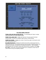
RUN TIME HOURS TRACKER 

PURGE AVERAGE RUN HOURS PER DAY 

– 

This will display the Purge

’s average 

hours run per day on a 14-day rolling average. 

PURGE TOTAL RUN TIME 

 Displays the total time the purge system has been 

running overall.  The time is formatted in Months, Days, Hours, Minutes. 

PURGE RUN HOURS 

 Displays the number of hours the purge ran during the current 

week, and the week before. 

MACHINE RUN HOURS


– 

Displays the number of hours the external signal from the 

machine has been on.  If not using the external machine signal, the factory jumper wire 
will cause this counter to run whenever the purge is powered on.  When using the 
external signal from the machine, these times can be used to compare to the 

Purge 

Run Hours

” to see how much the Purge system ran in comparison to how often the 

machine was running and outputting a signal. 


Содержание PURGE Series

Страница 1: ... Purge Operator R04 INSTALLATION OPERATION MAINTENANCE MANUAL MP Systems 34 Bradley Park Road East Granby CT 06026 USA Phone 1 877 689 1860 Email mpteam mpsystems net PURGE Series ...

Страница 2: ...engineers sales team and manufacturing personnel MP SYSTEMS high pressure coolant systems accessories are low maintenance and longer lasting MP SYSTEMS prides itself on building and supporting a dependable product Our team works closely with CNC machine tool manufactures distributors and customers to provide excellent customer service These relationships facilitate superior application experiences...

Страница 3: ...it Add Mounting Bracket to Install Kit 9 9 19 02 Update PLC screens to match V6 20 Removed Drive Tuning Instructions Add info on 480 400V system 6 4 20 B Jalbert 03 Update dip tube info and quick start guide details Removed settings for FM5 8 Manifold Added filter selection guide 6 23 21 K Quintin 04 Fixed info on 480VAC specs Updated quick start guide and install info Updated start stop mode of o...

Страница 4: ...ivery Checks 11 5 2 Transport Carriage 11 5 3 Storage 11 6 Installation 12 6 1 Install Kit Components 13 6 2 Recommended Tools for Installations 13 6 3 Electrical Installation 15 6 3 1 Selecting Voltage 15 6 3 2 Power Harness Installation 16 6 3 3 Control Signal Installation Optional 17 6 4 Inlet Installation 18 6 4 1 Inlet Suction Dip Tube 18 6 5 Return Installation and Hose Routing 21 6 5 1 Retu...

Страница 5: ... Purge Operator R04 8 Maintenance 34 8 1 Routine Maintenance 34 8 1 1 Filter Bag Replacement 35 8 1 2 Filter Bag Selection 36 9 Spare Parts 38 10 Schematics and Diagrams 39 ...

Страница 6: ...ccordance with authors rights MP SYSTEMS does not accept responsibility for any inaccuracies contained in this manual whether due to errors in printing or transcription It furthermore reserves the right to carry out such modifications to its products as it considers necessary and or useful without compromising their essential characteristics MP SYSTEMS does not accept responsibility for improper u...

Страница 7: ...angerous voltage Failure to heed this warning carries a risk of injury or death WARNING Indicates a possible danger situation Failure to heed this warning carries a risk of injury INFORMATION Indicates important information or advice on the use of the machine FLAMMABLE Indicates possible flammable material LOCK OUT TAG OUT Lock Out Tag Out Purge Series before service can be done ...

Страница 8: ...the instructions contained in this manual Always keep a copy of this manual near the machine Carry out routine maintenance operations with great care have worn or damaged parts replaced by qualified personnel and use original parts or those recommended by MP SYSTEMS To function correctly and for operator security the Purge Series must be operated with all panels in place and secured Dangerous volt...

Страница 9: ...tection when handling coolant cutting fluid 2 3 Prevention of Electrical Risks When power to the machine is switched on the machine is a source of danger especially if the basic safety rules are not followed In order to avoid any possible danger it is necessary to observe the following basic operation rules When making electrical connections to the Purge Series observe state and federal electrical...

Страница 10: ...comes out of the tool or nozzle falls down with chips goes through chip conveyor and goes into a collection funnel in the dirty side of the tank The Purge system pulls in coolant and chips from the funnel at a rate faster than is being provided This creates a difference in fluid level between the inside and the outside of the funnel pushing chips towards the Purge collection dip tube The fluid wit...

Страница 11: ...o easily pull power from machine Auto start on power up feature or scheduled clock run function Hour counters for filter run time vs machine run time optional 2 Year Parts Warranty Purge Benefits Clean coolant lasts significantly longer Less wear tear on machine and components Greatly extend time between tank cleanouts Prevent unexpected coolant related shutdowns Overall cleaner machining environm...

Страница 12: ... enabled to allow the purge to run automatically when powered up Another option is to run the filter on a scheduled Real time clock timer Refer to the quick start guide and PLC settings section for more information The alarm circuit interface with the machine is not typically required but is available if desired Typically customers will rely on the status indicator light on the control box to tell...

Страница 13: ...htly more difficult since the fluid will not drain out of the bag as easily Try starting with 15psi and either increasing the max pressure or decreasing depending on how filter change experience is Larger particles that are more porous as they accumulate will tend to fill the volume of the filter bag more These chips are sometimes so porous that they do not create enough detectable back pressure b...

Страница 14: ...480V FLA Full Load Amps Largest Load for determining power service requirements 4 1 Electrical Specifications MODEL FLA 208 230VAC Standard VAC kVA FLA 480VAC USEABLE 400V 5 CONTROL SIGNALS ALARM CIRCUIT Purge 8 5 3 2 4 0 Fused 24VDC NC NO COMPONENT ACCESSORY FLA 208 230VAC Standard VAC FLA 480VAC USEABLE 400V 5 HP RPM Feed Pump 8 5 4 0 3 3600 4 2 Mechanical Specifications MODEL LENGTH in WIDTH in...

Страница 15: ...10 4 3 Floor Layout ...

Страница 16: ...o not attempt to lift the machine with equipment that is inadequate or unsuitable especially with equipment that is too small for overall weight of machine Refer to Section 4 2 Mechanical Specifications for unit weight Only trained and licensed Fork Truck operators may transport this machine MP SYSTEMS is not responsible for any damage caused by unauthorized use WARNING Do not transport machine wi...

Страница 17: ...wer directly from machine Purge can be set to automatically run when powered on or with scheduled timer Status indicator light and HMI removes need for alarm interface with machine May require hole saws see appendix in back for more information The Purge requires roughly 24 x 24 of floor space that is located as close to the machine tank s coolant pump s as possible to allow for proper return flow...

Страница 18: ...s the correct location of the dip tubes is important to a successful install The best way to do this is to use a preexisting hole in the tank can be used to pass the various pipes through the tank top This is not only quick and easy but also gives you a perfect window to be able to see what is going on in your tank for troubleshooting Sometimes this is simply not an option and a hole must be drill...

Страница 19: ...ip tube you are installing to help layout where the hole needs to be drilled as well as where the fasteners will need to go for the clamp Use a center punch to locate the holes and prevent drill drift 2 Use the appropriate size drill to make a pilot hole in the center of the cut NOTE Only the drill should be used at this point do not use the drill bit while attached to the hole saw When the drill ...

Страница 20: ... Observe the technical supply conditions imposed by the power supply company 6 3 1 Selecting Voltage Many large industrial facilities run on 480v 3phase 60Hz electricity Most machine tools in the United States require a step down transformer as the machine tools typically run on 200 10 VAC 208 230v is the standard voltage for MP Systems units Optionally 480V units can be purchased voltage cannot b...

Страница 21: ...t hole and use supplied cord grip 2 Following local electrical codes install 3phase power to 208 230VAC line 480V optional The Purge is phased Red White Black Wire power cable in parallel with machine tool power Be sure to leave enough cable to properly ground the unit 3 Locate proper grounding point Attach using supplied ring terminals 4 Connect twist lock plug into receptable on bottom of Purge ...

Страница 22: ... length of cable to reach the Purge electrical panel terminal strip Install cord grip in bottom of purge e panel and route cable into panel Follow interface schematics and wire directly into terminal strip in purge e panel Remove pink jumper wire from Purge e panel terminal strip if using this function Locate the green light output from the machine Cut wire and crimp female tab onto output wire cl...

Страница 23: ...deal cases where some of the debris may be missed the Purge will still provide an excess of clean coolant directly to the clean side of the machine tool tank This will provide the machine tool with more coolant up time however you may have to clean out the tank periodically Also because of the Purge s high flow it will eventually capture debris that is in suspension even with a poorly placed dip t...

Страница 24: ...onveyor exit so large chips have a chance to settle to the bottom of tank before making their way into the suction inlet and clogging pump Suction inlet should be placed in path of coolant so that the purge will capture and filter out any suspended particles that would normally migrate towards the coolant pumps When possible use the supplied dip tube pipe assembly and green clamp to fasten to tank...

Страница 25: ...he fluid and directs it right into the Purge dip tube With a long exit or multiple exits along the same side some of the coolant at the far ends can be missed by the dip tube The purge will still work and will collect the majority of the debris but you won t have the same level of collection With two exits some of the coolant exiting the conveyor on the other side can be missed by the dip tube The...

Страница 26: ...ut try to use one farthest from the screen 6 5 2 Hose Routing The Purge uses a gravity based return Because of this the hose must be as short as possible and have a continuous downward slope as depicted in Example A below If the hose goes under the tank level or over the top of the Purge as depicted in Example B and C it can block the flow of coolant causing an alarm Use supplied T Bolt Hose Clamp...

Страница 27: ...hose to the feed pump outlet and to the purge tank manifold inlet and tighten clamps securely 3 Connect the 1 hose to the inlet of the feed pump but wait to connect the other end of the hose to the inlet dip tube until after priming pump 4 To prime fill the 1 inlet hose from the inlet dip tube end This will begin to fill the inlet hose and pump casting Continue filling until you see coolant begin ...

Страница 28: ...ing up the hoses or if it has already been installed by raising the dip tube out of the tank to make the pump suck air briefly 3 Turn on all of the coolant pumps in the tank You should see the coolant flowing into the clean section from the dirty section through the screen The coolant on the clean side of the screen will be lower than the dirty side 4 From the main screen start the Purge and wait ...

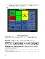
Страница 29: ...m will automatically run when powered on or when receiving an external run signal from the machine optional ALARM HISTORY Press to enter alarm history screen See below for more info SCHEDULED START STOP Press to enter scheduled start stop screen System runs on scheduled timer with real time clock See below for more info on how to set up FILTERS CHANGED If using the Filter Hours setting to alert th...

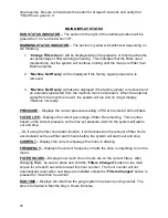
Страница 30: ...isplay machine not ready PRESSURE Displays the current pressure reading in PSI at the inlet of all four filters FILTER LIFE Displays the current percentage of filter life remaining This is either based on the current pressure vs the max set pressure at which the system will alarm out and stop Or if using the filter hour alarm function it will be based on the amount of filter hours accumulated vs t...

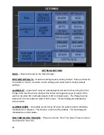
Страница 31: ...machine tool is desired this button can toggle the type of output of the alarm to be either NC normally closed or NO normally open The Purge must be powered on for this output to work in both cases The text displayed indicates the current status ALARM BUZZER An audible sound will go off when the system alarms indicating maintenance is required This function is turned off by default The text displa...

Страница 32: ...ents until the desired result is achieved 15PSI is usually a good mid point If the application creates chips that do not create enough resistance to flow to build up enough detectable pressure before the bag is completely full then the max psi should be greatly lowered or the Filter Hour Alarm function should be used instead of max psi MAX FREQ The maximum frequency in hertz that the pump motor ca...

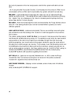
Страница 33: ...the machine tool is active The bottom setting labeled CLNT On Flow is not used in most cases other than swiss machines with small tanks using cutting oil This setting is used when the clean coolant pump section of the tank is too small to accommodate enough flow from the purge without overspilling but more flow from the purge is desired to keep the clean section full when the coolant pump s are ru...

Страница 34: ...ING Used to update Real Time Clock if it is incorrect START TIME Used to set time when the Purge will turn itself on Set to 00 00 to disable 24H STOP TIME Used to set time when the Purge will turn itself off Set to 00 00 to disable 24H DAYS OF THE WEEK Used to set which days of the week to follow the on off schedule ...

Страница 35: ...ber of hours the purge ran during the current week and the week before MACHINE RUN HOURS Displays the number of hours the external signal from the machine has been on If not using the external machine signal the factory jumper wire will cause this counter to run whenever the purge is powered on When using the external signal from the machine these times can be used to compare to the Purge Run Hour...

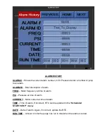
Страница 36: ... of alarm FREQ Motor frequency at time of alarm PSI Pressure at time of alarm CURRENT Motor current at time of alarm TIME Time of alarm If incorrect RTC can be updated in the Scheduled START STOP display DATE Date of alarm Again if incorrect update the RTC RUN TIME Amount of time the purge has run in total when the alarm occurred ...

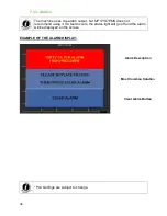
Страница 37: ... MP SYSTEMS does not recommend using it If a fault occurs the status light will go off and the alarm will be displayed on the screen EXAMPLE OF THE ALARM DISPLAY PLC Settings are subject to change Alarm Description Most Common Solution Clear Alarm Button ...

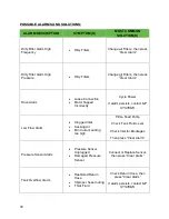
Страница 38: ...apped Incorrectly Cycle Power If alarm persists contact MP SYSTEMS Low Flow Alarm Clogged Inlet Sucking Air Min Current setting too high Prime Feed Pump Check Tank Fluid Level Check Inlet for Blockages Then press Clear Alarm Pressure Sensor Alarm Pressure Sensor Unplugged Damaged Pressure Sensor Connect or Replace Sensor then press Clear Alarm Tank Overflow Alarm Restricted Return Hose Improper ho...

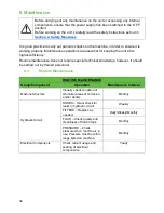
Страница 39: ... maintenance does not require special technical knowledge however it should be carried out by trained personnel 8 1 Routine Maintenance ROUTINE MAINTENANCE Group Component Operation Maintenance Interval Machine Structure Visually check condition of structure areas of corrosion and or dents Monthly Hydraulic Circuit HOSES Visual check for leaks in hydraulic circuit Weekly FILTERS Replace as needed ...

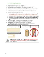
Страница 40: ...g neatly in basket For all bags ensure that the steel rubber seal on top of bag is seated properly on the basket groove and that there are no chips debris that will interfere with seal 7 Be sure O rings are re installed in outer groove and seat properly If there are any signs of damage or stretching replace O ring 8 Replace filter covers and secure the wing nuts snug by hand With good clean O ring...

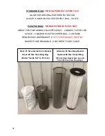
Страница 41: ...ing the entire bag s volume If longer filter life for finer particles is needed optional pleated cartridges with up to 10X the surface area for longer life and deeper baskets may be purchased separately If finer filtration is needed optional high efficiency bags and deeper baskets may be purchased Larger chips tend to fill the volume of the bag If coarser filtration to capture more chips and less ...

Страница 42: ...IS HIGH EFFICIENCY LONGEST FILTER LIFE 2 SIZE 5 MICRON PLEATED PAPER BAG COST REQUIRES 2 DEEP BASKET HF FILTER BASKET DEEP 2 BASKETS ARE REUSABLE ONLY NEED TO BUY ONCE Stock 1 Size Internal Cone Basket Stock 2 Size Steel Ring Bag Pulled Inside Out to fit Cone Alternate 2 Size Deep Basket Optional 2 Size Pleated Bag 2 Size Deep Basket Also Accepts Stock 2 Size Steel Ring Bags ...

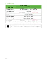
Страница 43: ...el O Ring M ORING Fuses ED 1A FUSE ED 1 2A FUSE Gauge H GAUGE 30PSI BK Inlet Hose Clamp s HC 2 HOSE CLAMP T Bolt Hose Clamp for Return HC 3 TS HOSE CLAMP Circuit Breaker ED CB 20A ED CB 10A For parts not listed please contact MP SYSTEMS at 877 689 1860 MP SYSTSEMS recommends stocking spare filter bags in multiples of 4 ...

Страница 44: ...39 10 Schematics and Diagrams 10 1 1 POWER SCHEMATIC 208 230V ...

Страница 45: ...40 10 1 2 POWER SCHEMATIC 480V ...

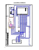
Страница 46: ...41 10 2 CONTROL SCHEMATIC ...

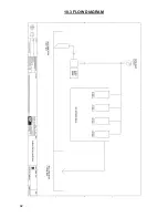
Страница 47: ...42 10 3 FLOW DIAGRAM ...

Отзывы: