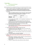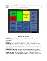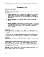
28
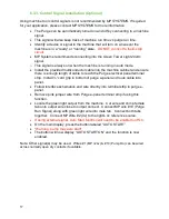
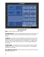
the current pressure vs the max set pressure at which the system will alarm out and
stop.
-Or- if using the filter hour alarm function, it will be based on the amount of filter hours
accumulated vs the set filter alarm hours before the system will alarm out and stop.
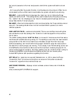
MIN AMP
–
(optional)
Minimum amperage the motor can run on before the Purge
alarms out and turns off. This setting can be used to detect when the pump is running
dry. Caution* dry run amperage is very close to slowest speed amperage and may
cause false alarms if not set properly.
MAX AMP
–
Maximum amperage the motor can draw before the Purge alarms out and
turns off. This setting should be set to 8.5A for 208-230VAC systems or 4.0A for
480VAC systems.
COOLANT ON FLOW
–
(optional-not required) This is a second flow rate setting that
will override the main flow setting if the
“coolant on” external signal from the machine
tool is active.
The bottom setting labeled
“
CLNT On Flow
” is not used in most cases other than swiss
machines with small tanks using cutting oil. This setting is used when the clean/coolant
pump section of the tank is too small to accommodate enough flow from the purge
without overspilling, but more flow from the purge is desired to keep the clean section
full when the coolant pump(s) are running. For example, main FLOW setting can be set
to 30GPM when the machine is idle, but when the machine
’s coolant pump(s) turn on,
and an external signal is wired in, the Purge will then use the
“CLNT On Flow” setting to
increase to 40GPM to accommodate the additional flow from the coolant pump.
Contact MP Systems with questions regarding this function.
OFF DELAY 2
–
(optional-not required) Settable timer, in: SS, to allow the Purge
“Coolant On Flow” to continue running for a set amount of time after an external
“Coolant On” signal from the machine drops out.
SOFTWARE VERSION
–
Displays current software version. Make note of Software
Version
when contacting
MP SYSTEMS
for support.
Содержание PURGE Series
Страница 15: ...10 4 3 Floor Layout ...
Страница 44: ...39 10 Schematics and Diagrams 10 1 1 POWER SCHEMATIC 208 230V ...
Страница 45: ...40 10 1 2 POWER SCHEMATIC 480V ...
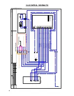
Страница 46: ...41 10 2 CONTROL SCHEMATIC ...
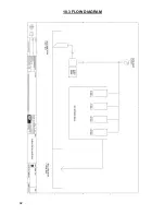
Страница 47: ...42 10 3 FLOW DIAGRAM ...


